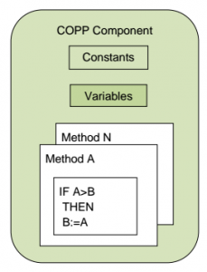
 A COPP component type is a combination of program code, data, and settings that defines a specific use.
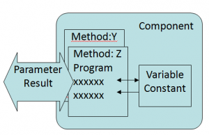
A COPP component type has a memory with variables and constants, that uses various memory types.
It also has methods with program code. The program has access to memory in the component. Also, it can call methods of its own and methods in other components through connectors. It is only these methods that have access to the memory.
A project can have many instances of the same component type. In that case, their variables are individually allocated in FLASH, volatile RAM, and non-volatile RAM. The type-information and program code of the methods are common.
All COPP types have a GUID (Global Unique Identifier) for identification, that VIGO6 assigns to all types.
VIGO6 GUIDs follow this format: <company identifier>_<ID number>-<version number>. So for example – GUID “PD_2886-01” is version one of type 2886 from company PD. Whereas GUID “PD_2886-02” is the second version of type 2886 from company PD.
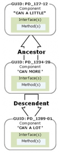
When you inherit from a component type, you create a new type with its own GUID. The new type is the descendant, while the other is the ancestor. You can add new elements to the new type. Further, the editor makes sure that it keeps all of its ancestor’s traits in order to stay compatible with its parent. However, you can’t change the parameter type for the ancestor’s methods.
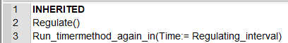
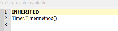
You can add more program code to ancestors by overriding ancestor methods in the descendant. The word “INHERITED” represents the code from the ancestor in the program code, and you can see it in the code window shown to the descendants. In the descendant you can choose to:
- Delete INHERITED – the methods from the ancestor chain will not be called.
- Add program code before INHERITED – The descendant code runs first, and then the ancestor code.
- Add program code after INHERITED – the ancestor code runs first, and then the descendant code.
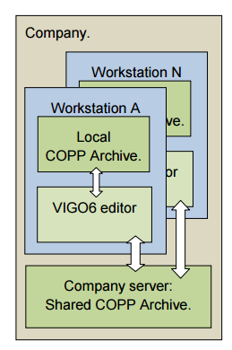
A VIGO6 installation comes with a company COPP-archive (also called Signer archive). This archive has all the COPP-component types that the company uses. This means both PD-developed component types and component types that the company has created.
The VIGO6 workstation installation has a local archive. Types in the local archive are classified as; Draft, Development, Deleted, Tested, Approved, or Archived.
This enables the VIGO6-developer to develop COPP-component types and store them locally as draft types for instance.
Once you have tested a component, you can archive it to the company server. In effect, the editor tags the component with the identification of the owner, a timestamp, and the status “archived”.
The type is now visible and useable to all other VIGO6-developers in the company. Developers can get a local copy by refreshing their local archives. Further, the local copies will have the same GUID as the one on the company archive.
If you make any change to an archived COPP component type, VIGO6 will create a new version of the type. Only the owner of a component type can create a new version. The owner can change ownership of a component type to another VIGO6-user, who then becomes the owner.
GUID states
Draft and the shared draft
A type in the draft state is local. It means that you only have stored your type on your workstation. As a result, another user from your company can’t see the type. When you want to delete a type from the draft, save, right-click on the tab, and click “Remove selected GUID from the archive”. From the draft state, you can change the state to Shared Draft to share it with other people. Sharing doesn’t mean that they can make changes to the type, it only means that they can view and use the type. You can only make changes to the types you own.
Put your draft in the shared draft
To put a draft into the shared draft state: First, you select the user(s) you want to share your draft with. By right-clicking on the type, and press “Select draft user”, and choose a user. Afterward, you click on “Draft” -> “Push type and doc. to signer” -> “OK”. You have now backed up your type on the server and shared it with the selected user(s). When you make changes to the type, you can push them to the server again to back up again. You can also change users again, but you need to push the changes. If you don’t select any users when pushing to the shared draft state, it works as a backup. Restore the backup from the server to the PC workstation by the “Restore type and doc.” command.
Documentation
When you push to the shared draft, you take a snapshot of your type with documentation. It will not create a new version. This is good if you are still at an early stage, and you don’t want to create a lot of versions. However, it can also be a problem because you can’t create a steady version that you can return to. For that reason, you can move your draft or shared draft to development. It is always a good idea to create a changelog each time you create a new version of your type. It is especially important when you work in the shared draft state since each snapshot overwrites the last. As a result, you can’t go back and check the differences between the versions.
Sandpit
You can’t make changes to a type that you don’t own. If you are not the owner of a shared draft or any other type you can put the type in the sandpit state. In the sandpit state, you can make changes to a type as if it is your own draft state. For example, you could try to add a new feature or fix an error. Afterward, you could suggest changes to the owner.
When you are done, you restore the type and documentation. All your changes will be removed when you leave the sandpit state. If the original type has moved to another state, you will download the type in the actual state. When the owner has implemented the changes, you can change to the new version. You can’t push a type with type references in the sandpit state. So use it with caution.
Delete
The only way to delete a type after the draft is through the Delete state. It is a state because you move the type to the deleted state. The type will be there for a certain time before it is deleted. If the server hasn’t deleted your type, you can put it back to the state it came from. The only type that you can’t delete is a type in the archived state.
Development
When you move a type to the development state, the type will be in version 1. You can’t make changes to version 1. In other words, it is locked. If you want to make a change, you right-click on the type and click “Create new version of type”. The new version will be in the draft state, and you can make changes. When the version is ready for development, you push the new version to the development state, and now both versions are in the development state. You can switch between the versions by right-clicking on the type and click on “open previous version” or “open next version”.
If you use a type in the development state in your project, and the owner creates a new version, you can’t know for sure that the new version will have the same functionality as the one you use in your project. For example, if you have a connector to a type in version 5, but you actually use the type in version 6, the editor will give you a warning. The reason is, that you can’t know if the type has the same interface in version 6. If you want that certainty – use an archived version of the type.
Tested and approved
You can’t put an approved type in the sandpit state or the deleted state, but you can move a type between the states tested and approved. You can change a type to the tested state when another person should test it. If that person, or another, approves it, you can move it to the approved state. If someone finds an error, it can be moved back to the tested state. In the end, if the type is ready, you can move it to the archived state that is the final state.
Archived
After you have put a type in the archived state, you can create a new version, but you can only add functionality to it.
The type itself can’t be deleted either. This means that you need to be very careful about changing the state of a type to archived. In effect, you don’t get type reference warnings when you use archived types, because you can be sure that the types still match after you change to a new version of the archived type.
The compromise is a trade of flexibility and speed in development for certainty and stability.
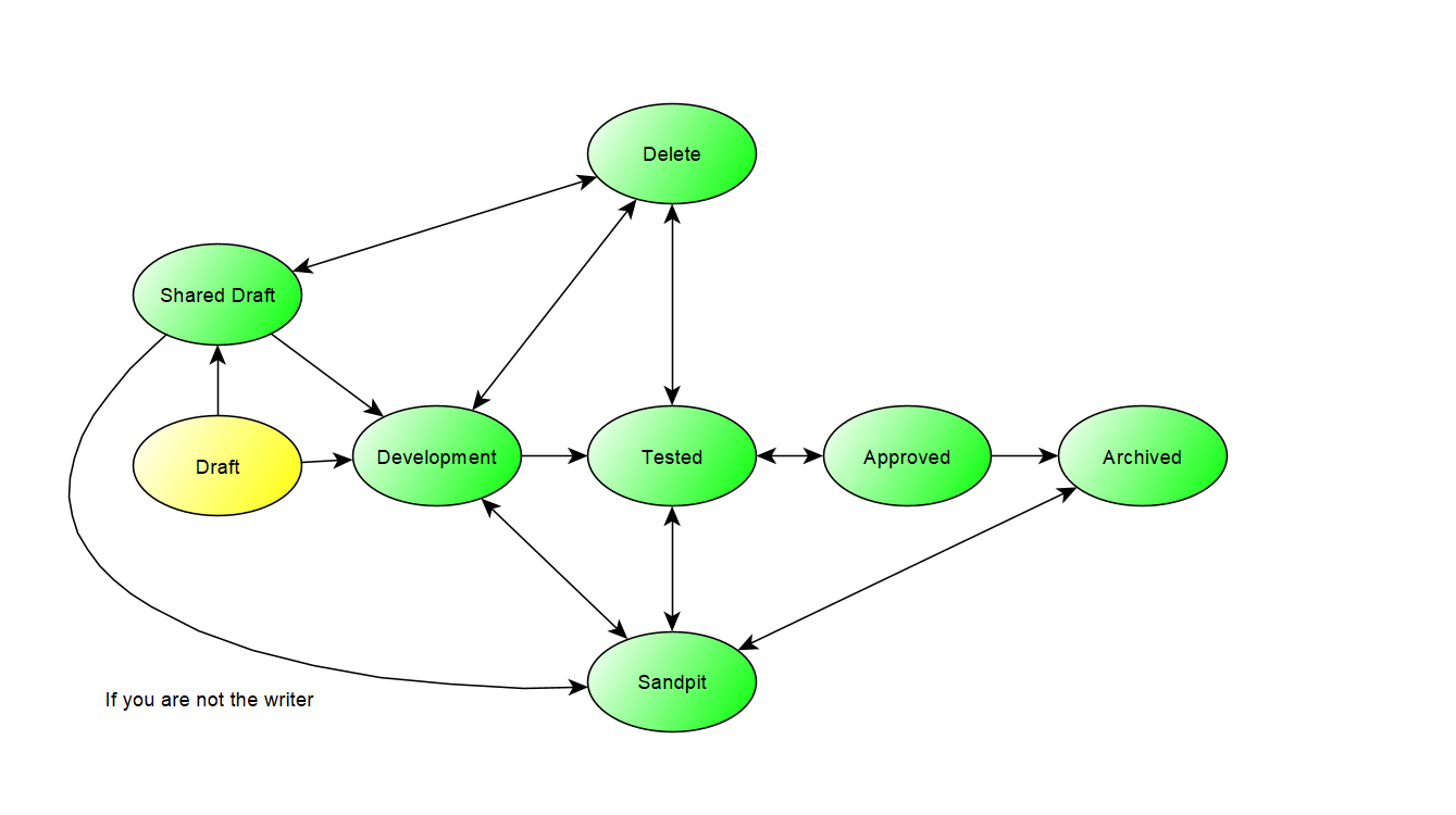
Yellow means that the type is local. Green means that you have backed the type backed up on the server. Note: You can only change the state from the shared draft to the sandpit if you are not the owner of the type.
Constants are either type constants or instance constants.
You define and set type constants at the type level. It means that you can’t modify them in instances of the type.
You define instance constants at the type level but set them at the instance level.
Variables can be volatile or non-volatile. While volatile variables lose their value on power off, non-volatile will keep them. Both are local to the component or method where you declare them. If you want to set or view them outside of the component, for example, you need to connect the variable to a Register.
Data instances can have a “quantity type”. In effect, visualization is simpler, and it enables the compiler to prevent quantity errors in your program.
Examples of Quantity types are:
• Density
• Pressure
• Energy
• Volume
• Mass
• Time
When you add variables of a floating-point type that represents a quantity, it is important to state the quantity type.
The compiler deduces the quantity type for the result of a calculation or expression. In effect, when you assign a value to the float, the compiler analyzes the quantity types and shows when there is an error such as
Volume = Density
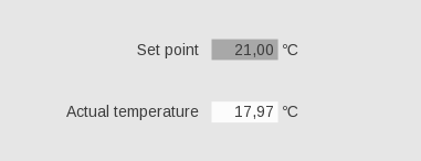
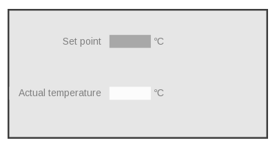
In addition, all data in a COPP component is stored in SI-units. A HMI convert between locally used units.
For example, when the operator changes a set point.
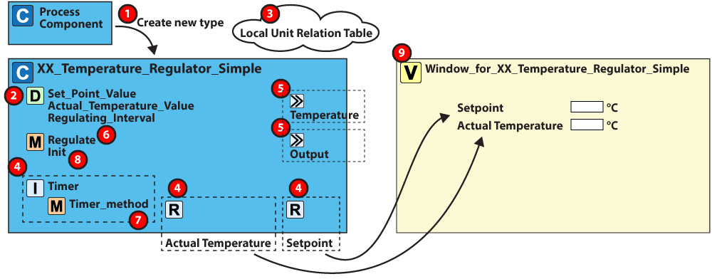
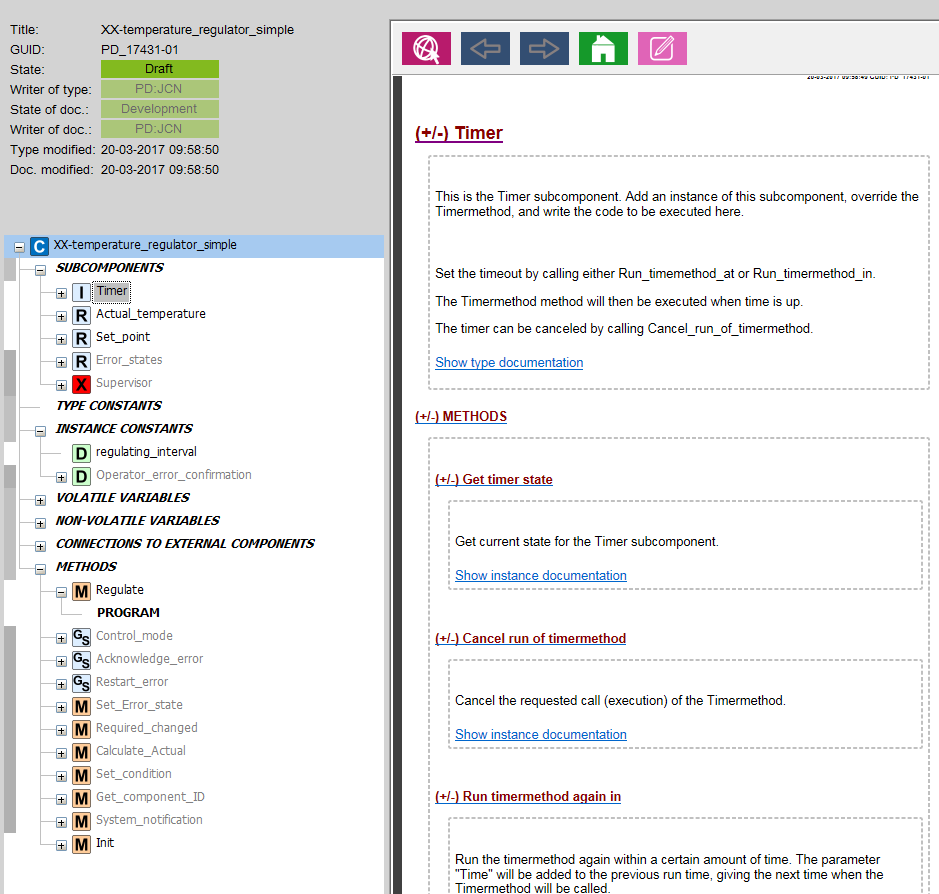
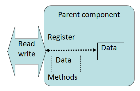 A special type of component that you can add to another component (the parent). A subcomponent defines an interface, as well as data instances. It has methods with access to its declared data structures.
By override, the methods can get access to the data in its parent. When a component as a parent adds a subcomponent, the parent has direct access to data in the subcomponent.
Examples are “register” and “timer”.
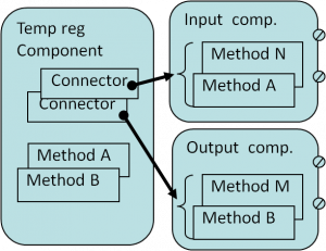 It is a feature in a COPP component type. You can use it to create a virtual connection between two components.
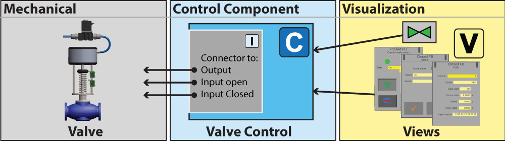
To illustrate the point, a method in the component called Temp reg Component has a connector to the components Input and output comp. As a result, Temp reg Component gets access to both their data and methods.
The connector is a “placeholder” for a connection to a component of a given type.
You don’t make a choice about the hardware for the components at this point. As a result, you can use the same control component with many (compatible) types of hardware. This means, that you don’t need to make new control code or views for each.
If for example, a specific hardware module for output control is out of production, you simply need to switch the physical module. Afterward, your plant can continue to run without writing new code or compiling your project again.
Definition
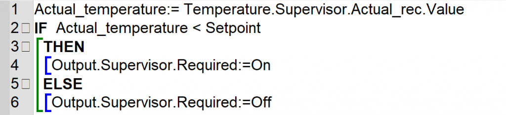
Methods have program code that only runs when you call the method. It is like a function in PROCESS-PASCAL, that can have parameters and a result.
Program code in a method has direct access to parameters, local variables, component variables, and constants. However, methods differ from functions, as you can call them via P-NET.
Method categories
• You can mark a method as internal (I), external (E) or both (I+E).
• You can call external methods from other components in the same device or via P-NET. External methods can’t call methods in other components.
• You can’t call internal methods from other components, but they can call methods in other components.
A method can call itself asynchronously (async).
The system only allows async calls, if the method you call has no parameters or result.
The system will interrupt the execution of an internal method in a component if an external method is called in the same component. Internal methods such as timers do not interrupt the execution of an already running internal method.
TIP: When you work with data that external methods can change, we suggest that you create a local variable as a copy of the data. You can then use this local variable in your method. Note that “set” on a register is an external method call.
We have made diagrams that show the communication between methods:
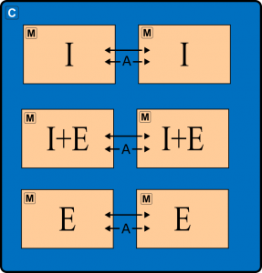 | 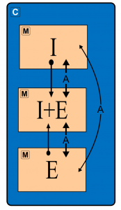 | 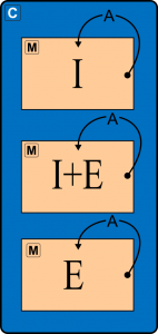 | 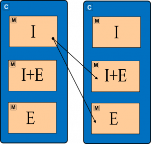 |
| Each method category can call a method of its own category in the same component both direct and async. | The different ways that each method category can call each other inside the same component. | Each method category can call itself async inside a component. | Only an internal method can call methods in another component through external connections. |
I=Internal, E=External, I+E=Both, C=component, M=method, and A=Asynch call.
A mutex makes sure that calls within a component to the same method are handled in sequence. Further, there is an external mutex that handles external calls to a method. There is no mutex for both internal and external calls, so be very aware when you use IE methods as conflicts in execution may arise.
When you define a method’s parameter and result type -you have to define the name, data type, and quantity type. It is the same as for a variable.
You have to include the individual parameters by name in a method call:
X: = Component Name. Method Name (Content: = delivered_amount, Number: = 7)
It makes the code easier to review. In addition, you don’t have to know the order of method parameters, as this will be clear from the parameter names. As a result, it can reduce the number of errors. The pop-up menu only shows the identifiers for instances of the data and quantity types you can use.
The editor has template functionality, which writes the parameter names, for example:
Method Name (Content: =?, Number: =?)
Methods may have local variables that only exist as long as the method runs.
You can give local variables a name and maybe a quantity type.
When you call a method, the system sets a local variable to “invalid”, and you have to initialize it in the code before you can use it. It makes your program more secure.
When a method makes a calculation, the data instance values and quality indications affect the outcome. It will be a part of the result of the calculation. In other words, if one or more is invalid, the result will also be invalid.

Video Title
Video Title
Video Title
Video Title
Video Title
Video Title
Video Title
Video Title