

Tutorial 9:
State machines
In automation projects, you often design systems with distributed process intelligence. As a result, your components can have a program sequence where earlier events determine the further program sequence. Such programs should be made as a state machine.
Motor control state machine
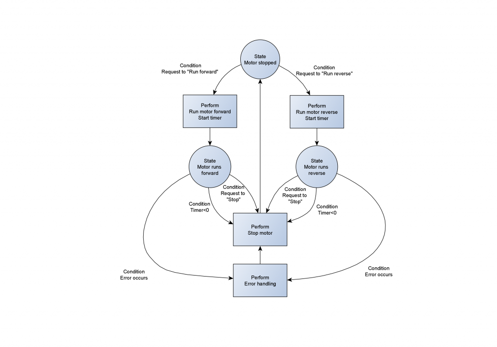
Figure 1. A state machine of a motor control.
1.
In a state diagram, you show a state as a circle with the name inside.
You can see our state machine in figure 1, we use three states – "Motor stopped", "Motor runs forward", and "Motor runs reverse".
2.
A state may have one or more conditions that cause a change to another state when the condition is true.
An arrow points to the next state.The system will stay in a state until that happens.
You show a condition with a text description across the arrow. The state "Motor stopped" has two conditions. The first is "Request to "Run forward"", while the other is "Request to "Run reverse"". When one of them is true, the state changes to either "Motor runs forward" or "Motor runs reverse".
Note that the condition is in the present tense. A condition may be "Start button is activated" or "Temperature > 23 degrees". However, it is not correct to write in the past tense, like "Start button was activated".
When you change from one state to another, the line passes a perform box. It holds a program flow to run when you change to the new state.
The program may have conditions that determine how to run the program, but the program carries it out straight away. It has no timers or other delay functions. The arrow after the "Perform" box shows the new state.
The perform box will either start the motor in the forward or reverse direction. The diagram also shows you need to request "Stop" before you can start the engine in the other direction.
Normally, when you start a timer, you use the Timer in the condition for the next state.
Implementation of the state machine
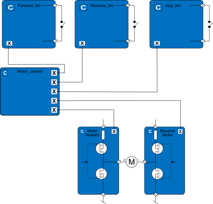
Figure 2. A diagram of the components that we use for our motor control, along with their hardware interfaces. C is a component. X is a supervisor or servant proxy. M is a motor.
In Figure 2 you can see a diagram of the components from the control of the motor, as well as their hardware interfaces.
The components for the buttons are general "Digital input process components". The components for the outputs to the motor are "Digital_DC_push_pull_output" components.
They are all servants for the supervisor Motor_control, where we have located the state machine.
In figure 3 you can see the tree structure of the project in VIGO6.
We have collected all the components in a control assembly "Motor_control_asm". We have located them in the device PD820.
PD610 is a communication gateway. It communicates with PD820 through Light-Link, and via PD610 to our COPP_PC_with_display, where we have a view.
Figure 3.
A picture of the project tree in VIGO6 with the assemblies, components, nets, and devices.

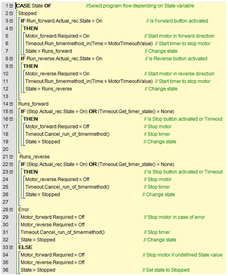
You can see the code for the state machine in figure 4. Actual_changed() and the Timermethod can call the state machine. When a user presses one of the buttons, the system will call Actual_changed(). While the Timermethod calls the state machine, when the time is out.
You should implement a state machine as a "case"-statement. It selects the program flow based on the state variable.
You control the program flow with the state variable. Make it an enum
type, where each value is the name of a state. Then your state machine
is easy to both read and use in a view.
The conditions from the state diagram are equal to the conditions in the IF statements.
Further, the perform boxes is equal to the code that runs when the conditions are true, after "THEN". Note that we also set a new value for the state variable in the end of a perform box.
Check the type PD_17236 if you want to explore the project further.
State machines in state machines
Now, it is your turn to make your own program using the state machine concept.
Specifications
What you need to build – Control logic
1. You need to build a project for a complete control system. One or more state machines should control the whole system.
2. Design your state diagram first.
3. The state machine should follow the criteria:
a. Use a case statement to implement the state machine.
b. Use an enumerated type for your state variable with meaningful text strings for each state.
c. Use at least three states.
d. There should be a condition for each state.
e. Use perform boxes that runs after the transition from one state to another.
4. At least two of the condition variables should be dependent on something from outside the state machine. Examples are from a view or another component.
5. The state machine should be event-driven. The maximum number of timers is one.
6. The system should include hardware modules with sensors, simulators, and/or actuators.
7. One or more components should use the supervisor/servant notification model.
8. Your control component should be able to serve as both a servant and supervisor.
YOU ARE NOW FINSHED WITH THE TUTORIAL!