Many readers have USB interface, and some of them RS-232 as well.
Depending on the type you use, it has to be connected to your control system in different ways. The USB-approach is the simplest, but requirements by the physical system, may give you only one or two options, and you may need to use the RS-232 solution.
HOW TO USE A BARCODE READER WITH USB
There is support for two barcode readers:
GFS4470 – USB interface with std. settings (USB-COM serial interface)
GD4130 – USB with HID interface (USB keyboard with standard key encoding)
Either of these can be connected directly to the USB-port of a PD688 or a PD802/PD803/PD804. The scanned strings can be accessed using the component PD_29592 – USB_text_input.
The USB_text_input is a process component, and your program will therefore be notified as a new barcode is read.
HOW TO USE A BARCODE READER WITH RS-232 VIA PD601
This tutorial explains how you can use a barcode reader with an RS232 interface with the hardware module type PD601 in VIGO6. Once you have set up the system, it can run without a PC. We expect that you know how to use VIGO5.9 as well as VIGO6.
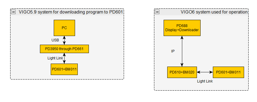
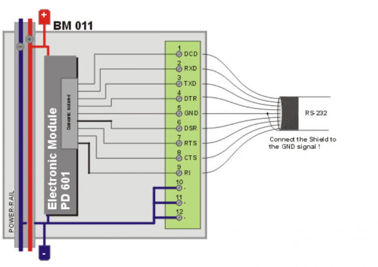
On Image 1 you can get an overview of how the system can be set:
Image 1: Overview of a sample system that uses a barcode reader with PD601.
None of the PROCES-DATA COPP modules for VIGO6 support RS232. On the other hand, PD601 supports RS232, but you program it with Process-Pascal in VIGO5.9. For that reason, you need two different software systems. In this sample system, we use VIGO5.9 to program the PD601 from a PC. Be sure to use the latest firmware version for PD601. You need to adjust the PD601 to be compatible with the VIGO6project. Important details are node addresses as well as the number of masters that VIGO6 sees. The Process-Pascal code must program the PD601 RS232 port to make it work with the barcode reader.
In the VIGO6 system, you can use a PC with a COPP PC with display or a PD688. How you use a PD688 as a downloader for your project is beyond the scope of this tutorial. If you want more information, see “How can I download new customware to a running system?”.The PD688 can talk with a COPP gateway like PD610, which again talks with PD601 through light-link.
Getting started
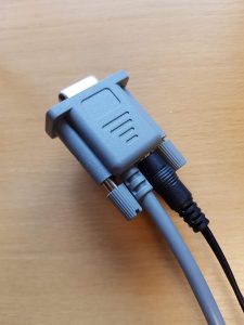
1. You can’t power the barcode reader from RS232, and thus you need a special cable that also has a connection to an external power supply.
You can see an example in Image 2.
Image 2: A DB9 RS232 cable with external power supply for the barcode reader.
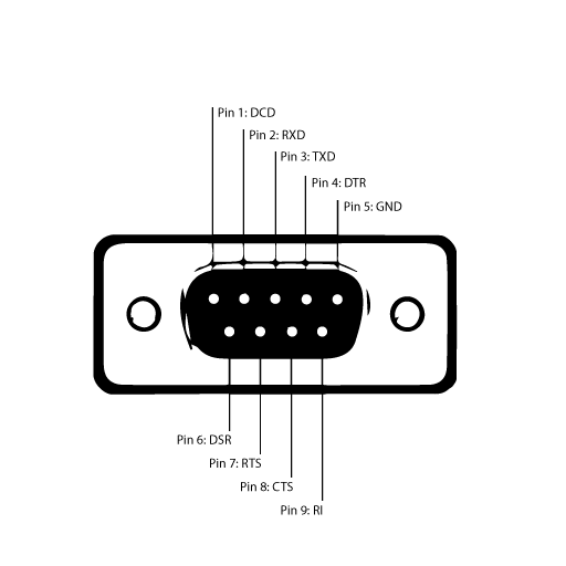
In Image 3 below, we have made a prototype adapter for the DB9 connector.All nine pins are used, but it may not be needed in all cases.
PD601 has the following pinout: Image 5: Pinout for PD601 from the official datasheet.
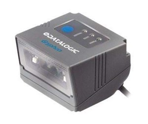
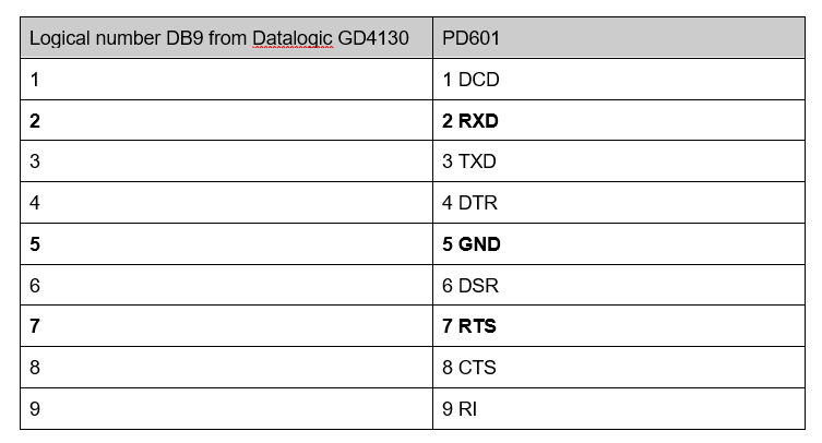
3. In the current sample system, we use a Datalogic Gryphon GD4130[1]. It comes with a default RS232 setting that only uses the hardware handshake RTS. In that case, we only need the pins 2 RXD, 5 GND, and 7 RTS. Therefore, we have bolded them in the following table. The connection from PD601 to the barcode reader is 1:1 and is therefore straightforward:
See the manual here, where the front page is in Portuguese, but the content is in English:
4. There is a detailed explanation in the manual of how to set up the barcode reader in the chapter Configuration using barcodes.
We followed, the suggestions on how to set up the barcode reader, and we chose the default RS232 setting without alterations. The setting values are as follow:
Baudrate = 9600 8 data bits 1 stop bit Parity = none Handshaking control = RTS
We prefer to use the same settings for the RS232 port of the PD601. For complete information about the RS232 port on PD601, refer to detailed information on our website:
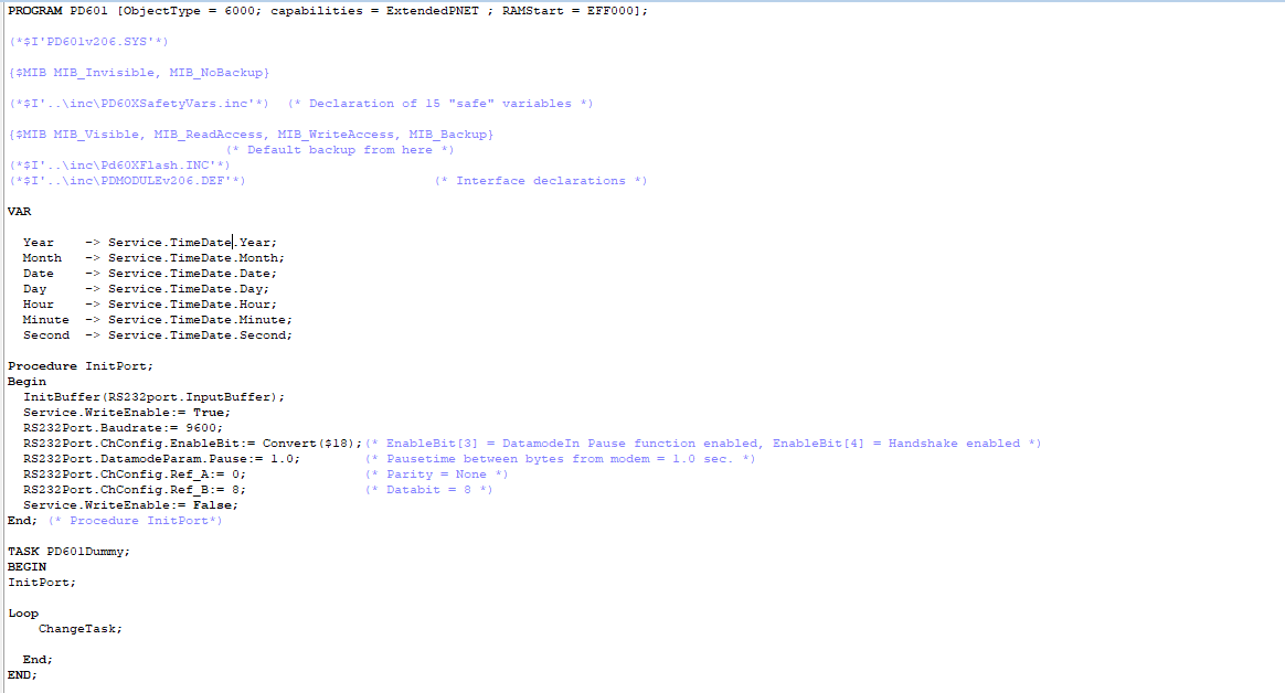
5. We configured the port from VIGO5.9 and Process-Pascal: You have to initialize The InputBuffer. We chose DataModeIn, since the OutputBuffer is not used.
You can use the modules PD661 Simple P-NET Interface and PD3950 USB to P-NET Interface for download of the program to PD601, as well as to get an overview of the various channels and their registers.
You have to initialize The InputBuffer. We chose DataModeIn, since the OutputBuffer is not used.
You can use the modules PD661 Simple P-NET Interface and PD3950 USB to P-NET Interface for download of the program to PD601, as well as to get an overview of the various channels and their registers.
Representing PD601 in VIGO6
1. When you have set up the PD601 to match the RS232 protocol for the barcode reader, you have to represent the module in the VIGO6 system.
For that purpose, we created a NON-COPPdevice. PD601 – GUID: PD_22880-0. PD601 is a NON-COPPdevice that represents the hardware module PD601. The module has several channels, but we only used Channel 0 – Service and Channel 1 – RS232Port.
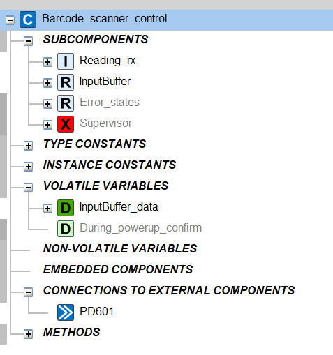
Image 7: A sample control component for a barcode reader.
2. We created a control component for our barcode scanner. In this sample project, we made a simple system as illustrated in Image 7 :
3. There is a connection to the NON-COPP PD601. We located the input register in the PD601 and noted its type. We used the same type to create a variable in the control component that is applied in the control logic, having the name “InputBuffer_data”.
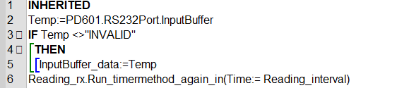
The timermethod has the name “Reading_rx” in the init function. The Timermethod has an override:
One thing to note is that when the InputBuffer is read, the PD601 removes the read element from the buffer. The system therefore stores the read value is in a temporary local variable, that we use to assign the InputBuffer_data variable.
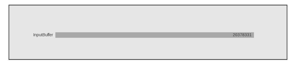
4. We can use the InputBuffer variable from the control component in a simple visualization. As an example, you can see Image 8, where we have scanned a barcode:
Image 8: A sample visualization using the data from the InputBuffer.