Now let's start with VIGO6 - What you need to build
In this first tutorial, we will show you some key ideas of VIGO6 that will help you build your first control component. The tutorial switch between theory and hands-on exercises with "HOW-TO" videos as a help.
THE Control logic
SPECIFICATION
The first tutorial is to create a TEMPERATURE REGULATOR by connecting a number of components and the related visualization.
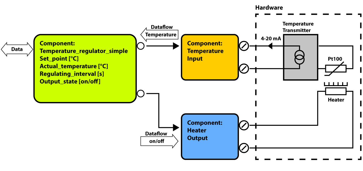
• A blue, already made digital output component to control the heating. • An orange, already made 4 – 20 mA input component to read the temperature. • And a green component to control the temperature regulation.
The regulator component must contain a temperature set-point and a regulating interval set-point.
The regulation is a simple ON-OFF controller without a temperature hysteresis.
When the temperature is below the set-point, the component shall turn the output, connected to the heating element, OM. When the temperature is above the set point, the output shall turn OFF.
The regulating interval is controlled by a timer. The visualization must show the current temperature and a set point that can be changed by the operator.
COMPONENT
A component in VIGO6 can be compared with an object in Object-oriented programming with own variables and methods containing program code. The variables and methods are encapsulated and there is only access from other components if enabled. Types are identified by a GUID, which is a unique identifier.
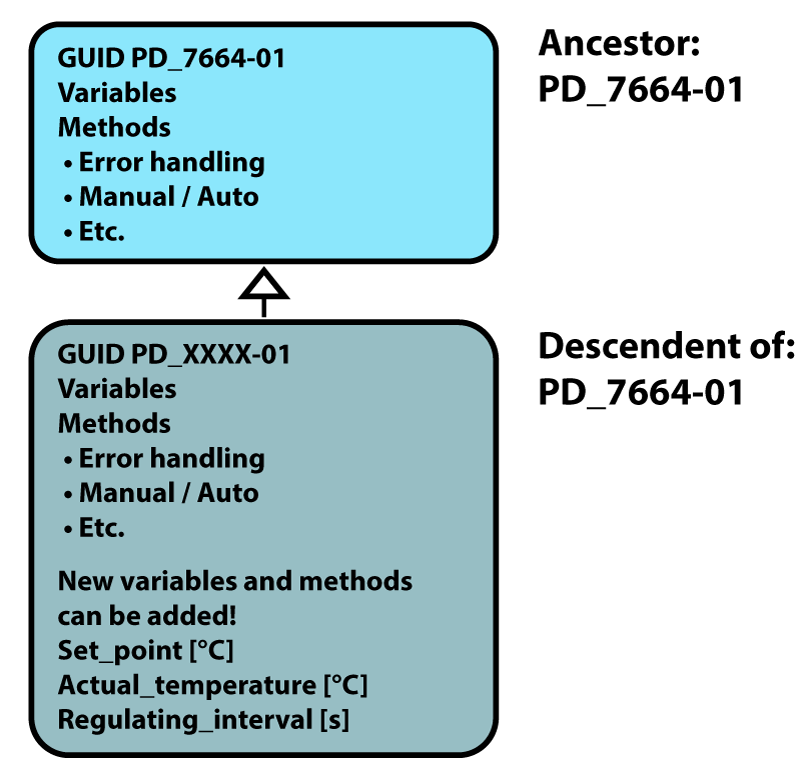
The format is: Company ID, underscore number, hyphen followed by a version number. Example with a Process component: PD_7664-01 This component includes error handling, Manual or Auto etc.
A new component is created as a descendent of another component, called ancestor. The new descendent component gets automatically its own GUID.
This new component has the same features as the component it was "created from", and in this new component, it is possible to add functionality to the features already implemented in the ancestor component.
1. Click on the “open” icon (or press “CTRL O”) in the VIGO6 Editor. Then select “COMPONENTS”. A component can be found in the list by typing any part of the name or the number. Open the PD_7664-47 in the Programmers catalogue by a double click. The Process component PD_7664 is used as ancestor for the Temperature regulating component.
2. Right-click on the component name and then select “Create new descendant of type”. A new tap will open with the new type, where you are the writer. If you are not a registered user, the Writer is Displayed as Unknown. Double-click on the name of your component and change it to “Temperature Regulator Simple”.
Note: When you press space, you make an underscore.
CREATE VARIABLES AND CONSTANTS IN YOUR COMPONENT
An instance constant holds a value, which the program can read but not write to.
4. Select a data type. In this case the Float32_PD 2003-02. It is a floating point format.
5. Change the name to Regulating_Interval. A quantity type specifies the units of the data. VIGO6 is using SI Units but the visualisation can convert to other units.
6. Right-click on the variable and select "Quantity type".
7. Select Time_Difference_PD_3737-01, which has the SI unit second.
ADD A VOLATILE VARIABLE
A volatile variable loses its value under power down. After powerup it is set to an ‘Invalid’ value.
5. Right-click on the variable and press "Quantity type".
6. Select PD_3732-01_Absolute_Temperature. The SI unit for temperature is Kelvin, but the temperature can be converted by visualisation to °C or Fahrenheit._
ADD A NON-VOLATILE VARIABLE
SEE THE HOW-TO VIDEO
A non-volatile variable keep its value after a power up. 1. Right-click on the section "NON-VOLATILEVARIABLES". 2. Add a variable to hold the setpoint for the regulator. 3. Click on "Add variable" 4. Select Float32_PD_2003-02. 5. Change the name to Setpoint_Data. 6 Right-click on the variable and press "Quantity type". 7. Select PD_3732-01 Absolute temperature. 8. In the right side, set the default value to 25 °C. It holds the set-point for the regulator.
Play Video
Tutorial 1 - STEP 2 CONNECTIONS TO OTHER COMPONENTS
Your temperature regulator component will need to interface to the orange temperature input component and to the blue digital output component.
In this case two connectors are required. One for the temperature and one for the output.
A connector is used to communicate with other components. The connector is created to be connected to a specific "interface", which can be a data-type or a component type.
Via this connector the external interface can be accessed.
Right-click on "Connections to external components".
2. Add Connector to component of type: a. Digital output base PD 2824, which is a basis for more output types. b. Rename it to Output.
3. Create a connection to a temperature component: a. Right-click on "Connections to external components" b. Add Connector to component of type: Temperature Input Base PD 2854. c. Rename it to Temperature.
REGISTER
The data in a component is encapsulated and has no external access to data from other components, but we can make the variables Setpoint Data and Actual Temperature Data accessible outside the control component for example from visualization and for other components by using RegisterSubcomponents.
This is done by adding a register and assign it to the Set-Point Data. The same for the Actual Temperature Data.
ADD A REGISTER
ASSIGN DATA TO THE REGISTER
1. Right-click on the subcomponent section of your component and select: 2. Add>> Register>> click on PD 4050 Register. 3. Change the name of the new register to Setpoint.
This is used to calculate the number of digits to show. The maximum value and the minimum value are set according to the value range the variable can be.
In this case the maximum value is set to 100 and the minimum value to zero but first check the Define value range box.
The visualization is using Alarm limit high and alarm limit low to indicate that the value is outside the accepted limits, by showing a red line around the digits. The editor adds automatically SI unit belonging to the selected quantity.
An operator has one or more functions in a company. For each register it is defined which functions the operator are allowed to access and whether read and write are allowed by enabling Get and Set. Default is Get and Set allowed for all functions. In this case don’t change that.
ADD THE NEXT REGISTER
Then create another register with the name Actual temperature for the variable Actual_Temperature_Data. 1. Right-click on the subcomponent section of your component and select: 2. Add>>, Register>> click on PD_4050 Register. 3. Change the name of the new register to "Actual Temperature" 4. Right-click on the register and click: "Assign data field to the registersubcomponent". 5. Select Actual Temperature Data as the register variable. 6. Set the maximum value to 100 and minimum value to zero. 7. Set the alarm limit high to 40 and alarm limit low to 10. 8. Enable "get" and disable "set" for all operator functions. This tells the view that this variable is read-only, and nobody can change the data from the visualization. The group of external accessible data and methods is called an interface
ADD A TIMER
SEE THE HOW-TO VIDEO
The regulation method must be called with a specified interval. For this a timer is used. 1. Add “Timer subcomponent” PD 4404 to the Subcomponent section. 2. Change the name to Timer. 3. Click on the timer.
Now you need to write the actual piece of code that will enable your component to make the wanted regulation.
CREATE A NEW METHOD
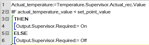
1. Right-click on the method section and select "Add Method". 2. Name it Regulate. 3. Write code for your temperature control: a. You can right-click and use "select identifier" and "code templates" instead of writing all the code yourself. b. Read the temperature from the input component into the data "Actual Temperature Data" in the control component.
If the temperature is lower than the set point, then set the output. In all other cases clear the output.
REPEAT THE REGULATION
OVERWRITE
An ancestormethod can be Overridden, meaning that you can add code to the method.
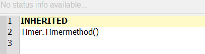
Once a method is “Overridden”, the method will contain the keyword INHERITED, representing the code implemented in the ancestor.
By creating a descendent of a type, you also get already implemented methods which can be used directly as base to which functionality can be added.
INTERVAL
The regulation must be kept running with specific intervals, and for this, you use the timer subcomponent that you added earlier. The interval must be defined to 0.1 seconds, in the instance constant.
Insert your program: 1. Fold out the Timer subcomponent in your component and select the Timermethod. 2. Right-click to ‘Override’ and open "Program". In the first line of the program, it says INHERITED, representing the method code of the ancestor. Don’t delete the INHERITED, unless you know what happens in the code from the whole ancestor chain.
CREATE THE PROGRAM CODE
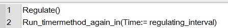
Create the program code that: 1. Calls the Regulate method you have made. 2. Calls the Run timermethod again, with instance constant Regulating Interval as parameter This is what your code should look like.
INIT
You need to be sure that your system is in a known state before you start your regulation.
After power up, the init method in the methods is called automatically.
The method Init(), cannot perform any kind of communication with other components and are used for presetting data in the component.
Just after Init(), where the primary start-up is done for all components in the device, the method After Init() is automatically called. This method may communicate externally (via a connector).
Override this method to set an output in a specific state as an example.
You have to add your code to the init program: 1. ‘Override’ the After Init method in your Temperature Regulator Simple component. 2. Call the Timermethod after ‘Inherited’
This is what your code should look like:
SEE THE HOW-TO VIDEO
Play Video
Tutorial 1 - STEP 4 VISUALIZATION
Data in a component can be visualized, but only data assigned to a register or GET SET methods, where the checkbox Allow access to register and methods marked with external access are checked.
The Temperature Setpoint and Actual Temperature in your component are already accessible from other components.
Let us make a simple view of our temperature regulator component. When creating a visualization for your component, it is created on basis of an already existing visualization for your component, or for an ancestor of your component. As the visualization must know the interface of your component, creating a visualization is different to creating a descendent of a component.
CREATE A VIEW OF THE TEMPERATURE REGULATOR COMPONENT
Your component should be able to view and change the set-point and to view the current temperature.
Open your control component Temperature Regulator Simple. A view is created as a descendent of another already existing view, in the same way as you created your component. 1. Right-click and pick “Create new view for this type based on” PD_11813-_Comp_view”.
When creating a visualization for your component, it is created on basis of an already existing visualization for your component, or for an ancestor of your component. As the visualization must know the interface of your component, creating a visualization is different to creating a descendent of a component.
By selecting the viewancestor in the component, the new view will automatically get component as for-type. 1. Rename the view to “Window for temperature regulator simple”. 2. Save your view.
Open your graphical editor by pressing the “Show view”-icon seen to the right. It is just above the VIGO6 navigation tree and looks like a play button.
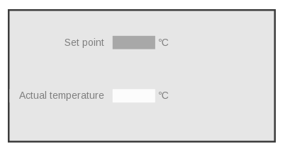
You now see your empty view. 1. Adjust the view size, by right-click on the shown view, and adjust the view size here. Set bottomRight y to 50 mm and x to 100 mm. 2. Add the values to show. 3. Right-click on the view list and pick “add” – “view for control instance”. 4. Click on the plus sign next to ”Temperature Regulator Simple” – This selects a component instance, one out of many in a bigger project. 5. Pick register “Setpoint” – That selects the register in the selected component instance, one out of many in a bigger project. 6. Select in Programmers catalogue view PD 2159 – Number Name Value Unit – This selects how the data assigned to the register is represented in the view.
On your view, you now see the element and you can drag it where you want on the screen.
Add a similar view for the register “Actual Temperature”.
Finally, you have created your control component with control logic and a view. You can use it again and again.
LET’S SUMMERIZE
SEE THE HOW-TO VIDEO
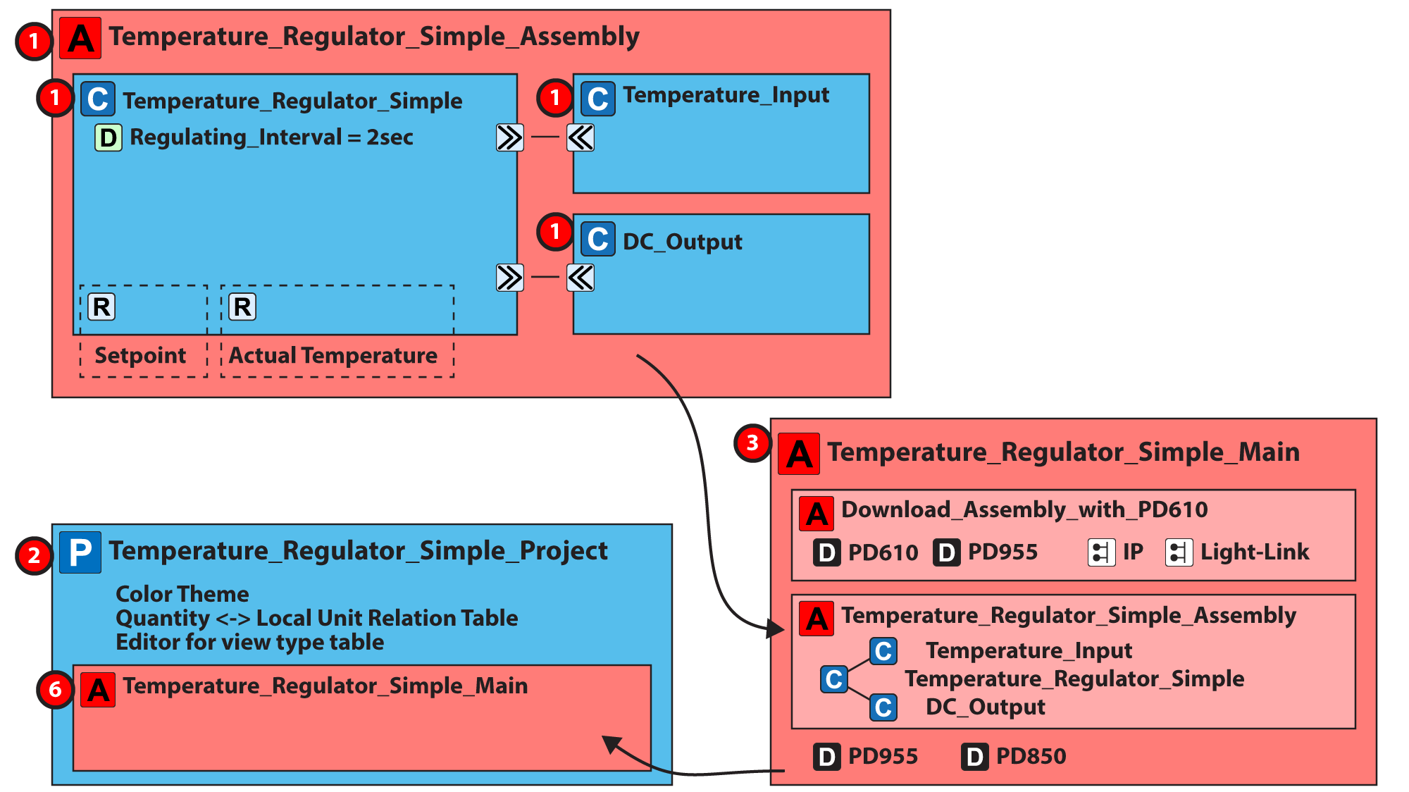
And to recap, here’s what you’ve built:
The numbers on the illustration below correspond to the steps that we have just gone through.
Play Video
Now let us move to the next tutorial where you learn how to create assemblies, main assemblies, and projects. And you will set up your testbed and load your components into a hardware module.