DRAFT

Tutorial 2:
Assemblies and projects
In this second tutorial, we will again present some of the key concepts of VIGO6. Further, you will learn how to use your component and locate it in hardware.
First, we will use the component we created in tutorial 1 and use an instance of the component in a control assembly.
Next, the assembly gets located in the main assembly, that we add to a project. Last, we will run our program on a testbed.
The figure below shows what you will build in this tutorial. The red dots show the steps.


The tutorial switch between theory and hands-on exercises with "SEE HOW IT WORKS" videos as a help.
Concepts
Throughout the tutorial, you need an understanding of the following concepts:
A normal mechanical assembly (see the diagram) specifies some mechanical parts and how to join them. You can use it to produce many units of the same type.
A COPP–assembly type is similar. It specifies some COPP-types and their connections that perform a certain function. It could be a mixer of tanks, valves, and recipes for example.
MAIN ASSEMBLY
The main assembly can contain:
– Components
– Other assemblies
– Devices (representing physical modules)
– Nets
– Clusters
The assembly shown in the diagram has the instances: two assemblies of Z-type, component Q, device W, device Y, and Net H.
The components are located in devices, as guest components, that use the memory and CPU of the device to run the methods.
In addition, the COPP-type “net” represents the physical P-NET that supports the protocols Light-Link, RS485, and UDP on Ethernet.
When you connect devices to a P-NET, the system gives a node address to the device on the net. When you visualize a P-NET, the view will show the devices that you have connected to the net.
A module is a piece of hardware with firmware, both of which PROCES-DATA has created. It can execute the VIGO6 code (customware).
In COPP, a hardware module is represented by the COPP-type “device“. A module has a CPU and different kinds of memory. It can have I/O‘s with electrical connections to the plant. Further, it has firmware and you can add guest components in the form of customware. You will often want to distribute the control system “intelligence” into more than one module.
You specify the overall automation of a plant in a project.
A project is not a COPP type, so you can’t work with inheritance on projects. But you can make copies of projects.
To summarize, the content of a project include:
- The main assembly, that describes the automation in terms of control components, assemblies, devices, networks, and views.
- Physical information:
- Name of the company
- Address
- Phone number
- Internet IP address
- The look and feel of the user interface for the automation program:
- Color theme
- Local unit table
- Languages for views.
- Serial numbers for devices.
In your project you need a main assembly, with the control components, interconnections, and devices you need to build and run the plant automation.
Languages, units, color themes, and module serial numbers are seperate from the control logic. As a result, an assembly can be reused without any customization or recoding in different locations or even countries. You can create different projects and add an assembly instance to each project.
Step 1 - Create an assembly
1. The first step is to create an assembly for the temperature regulator:
a. Select ‘Create new type’ on the main button menu and select ‘Assembly’.
b. Rename to XX_Temperature_regulator_simple_assembly.
2. Add and setup the control component.
a. Right-click to add an instance of your control component (XX_Temperature_regulator_simple) to your assembly.
Note that variables are no longer visible and that you can only see external methods. You can still see the instance constant, the registers and the connectors.
b. Set the instance constant "Regulating_interval" to 2 seconds.
3. Add Temperature input
a. Right-click to add an instance of temperature input transmitter interface PD_2855 Temperature_input_4_to_20_mA.
b. Rename to "Temperature_input".
4. Add DC Output
a. Right-click to add an instance of the output interface PD_2823 Digital_1A_DC_output.
b. Rename to "DC_Output".
5. Connect the components
a. Now, find the control component instance and right-click on the Temperature connector and connect it to the just added temperature input transmitter interface.
b. Connect Output in the same way to DC_output.
Note that the editor only lets you make a connection to a component of the type you have specified
SEE HOW IT WORKS
Step 2 - Create a main assembly
Now, we have an assembly with our control code. Further, it has interfaces to the outside world – the input and output. As a result, we are ready to decide which modules and networks we need to run our setup.
This we define in the main assembly.
1. Create new type – Assembly – rename it to XX_Temperature_regulator_simple_main
2. First, add the assembly PD_15858 Download_assembly_for_tutorial to your main assembly.
The assembly has a COPP-PC device that you can use as a downloader of customware. Further, it has a PD 610 COPP–device that you can use to establish an Ethernet connection.
3. Next, add your assembly: XX_Temperature_regulator_simple_assembly
4. Add the device PD850, with GUID PD_23221 – PD850_MF_IO, and rename it to PD850
For this tutorial, we will use a PD 850 Multifunction module.
It has analog and digital I/O as well as a processor. In effect, you can locate all your components in it.
5. Connect PD850 to the Light-Link net
a. Press the plus sign next to the PD850.
b. Press the plus sign next to "NET TERMINALS".
c. Right-click on Light-Link.
d. Press connect and choose Light-Link in the assembly "Download_assembly_for_tutorial".
6. Add a PD_955_PC_w_display and name it "COPP PC with display". This is the device that will run your view
7. Connect the COPP PC with display to the IP/Ethernet net
a. Press the plus sign next to the COPP-PC to fold it out
b. Fold out "NET TERMINALS".
c. Right-click on "LAN".
e. Press "Connect" and choose "IP" (Ethernet) in the assembly "Download_assembly_for_tutorial".
SEE HOW IT WORKS
Step 3 - Locate the control components
Now you need to locate your software components.
1. Click on the PD 850 device. Double-click on the components in the "Not located elements" in the properties area to the right, and they will move to the "Located elements".
SEE HOW IT WORKS
Step 4: Setting up your test environment
1. You need a 24V power supply, PD 850 with the base module BM104, a PD610 with the base module BM020, and a V6_COPP_DEVICE.exe
a. Connect the base modules with the COPP modules
b. Connect power from the PSU to BM020
c. Add a power rail from BM020 to BM104
2. Connect one input, in the form of a 4-20mA slider,
to terminals 10 and 30 GND
3. Connect one output, it can be a green or red LED,
to terminals 01 and 21 GND
4. Install your COPP_PC PD955.
a. Copy it from the USB-device to your hard disk.
b. Run the installationprogram, and the COPP-PC will be installed on your PC.
c. On your windows Desktop, please find and start V6_PC_DEVICES_boot. Only nessary this very first time, or until the windows PC has been restarted once.
d. Now you have a small launch icon on your windows taskbar.
Here you can start and stop (Manage) the differend COPP-PC decice(s) installed. Each device will be individual named and the serial number will be part of this name. (Ex. Sno_10808182).
Serial numbers, modules, and devices

We call the physical hardware module, as PD610 for a module.
The representation in VIGO6 is a device. The serial numbers on the modules
are eight digits numbers, and you can find them on the modules next to a
barcode. In the picture to the left, it is inside the yellow box.
For a COPP PC, the serial number is the name of the folder with your COPP PC. When the PC-device is running the serialnumber is shown in the top bar.
You can insert serial numbers from the project view. First, you find and click on the device. Next, you find the serial number input text field in the properties area to the right in VIGO6. Last, you insert your serial number. You update the serial number for the device when you save and build your project.
The serial number for the custom COPP device, you get with your VIGO6 license is 20327971.
SEE HOW IT WORKS
Step 6: Setup your project
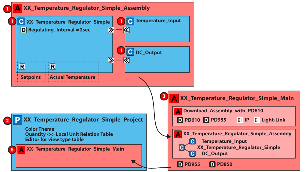
1. In your project, add your main assembly "XX_Temperature_regulator_simple_main".
2. Select the downloader device
a. Find the "Project Downloader device" in the "Download_assembly_for_tutorial" assembly.
b. Right-click and set it as a downloader.
3. Right-click on your main assembly and press "open type".
This changes your perspective to the main assembly.
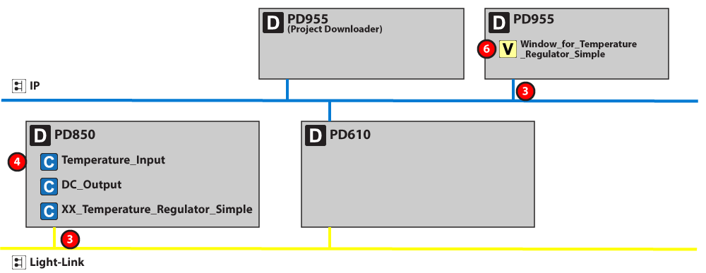
4. Now that you are in the main assembly, add your view "Window_for_XX-temperature_regulator_simple" as a guest view on the device "COPP PC with display".
a. Fold out the device, embedded components, and display screen.
b. Right-click on "guest view" and "Select root view for display"
c. Fold out your assembly "XX_temperature_regulator_simple_assembly", select your "XX_temperature_regulator_simple" control component, and find your view under visualization and draft types, and double-click to select.
5. Find back to the project, by clicking back
(Ctrl+B or using the Back button)
6. Set the serial numbers for your devices – PD 850, PD 610, COPP-PC, and project downloader device. The serial number for the project downloader device is 20327971.
7. Save and build.
8. Power on the modules.
9. Connect PD 610 to the PC via an USB-Ethernet Adaptor.
We suggest D-link-1312, or ThinkPad USB 3.0 Ehernet AdaptorPN: RTL8153.
10. Start the COPP-PC
a. Click on the "Manager V6_PC_DEVICES Device", and find the COPP PC-Device you want to start, and start it.
PLEASE NOTE: The "How to do it" in Step6 and Step 7 is united in the video under Step7

Step 7: Download your code and test your regulator
1. Press the "Start project downloader" button.
A system window opens
2. Press "config all modules"
a. Wait for the program to finish
b. Check that there are no failed modules.
Now your code is loaded into the modules.
Your display PC will show you the view, and you can change the input by moving the potentiometer.
3. Change the setpoint by keying in a value.
4. See how the output indicator change from on to off, depending on the temperature and the setpoint.
SEE HOW IT WORKS