Tutorial 4:
Introducing the proxy notification-model (supervisor/servant)

In this tutorial, we will explore the PD_7664 process component. We will build a temperature regulator like in tutorial 1, but now we want the control code to run when the temperature changes. As a result, we will use the notification model.

WHAT YOU NEED TO BUILD – CONTROL LOGIC:

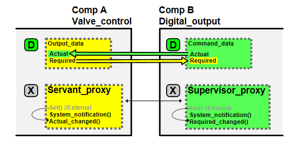
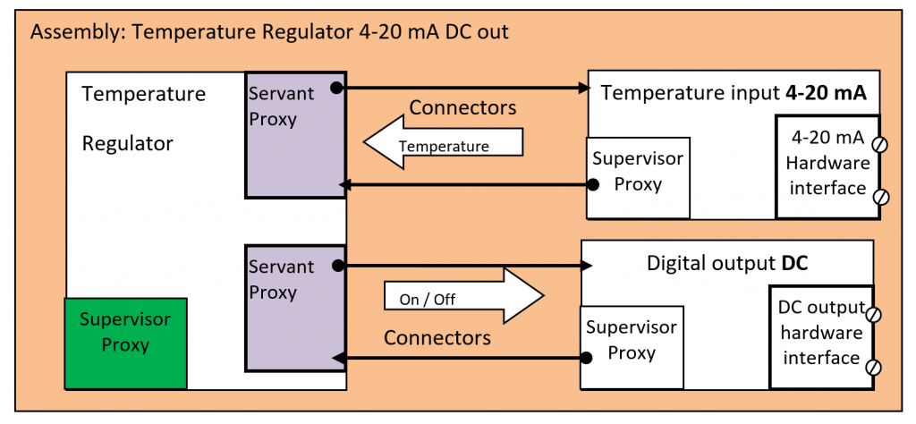
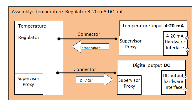
1. You need to build the light green component in the picture to the left.
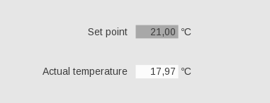
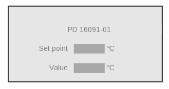
a. You set a setpoint.
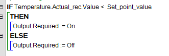
b. When the temperature is below the setpoint, the component should turn on an output that you connect to a heating element.
c. On the other hand, when the temperature is above the setpoint, the output should turn off.

2. You "measure" the temperature with a 4-20 mA temperature transmitter.

3. The regulation is a simple on/off controller with a temperature hysteresis. It must run every time the input temperature changes.

WHAT YOU NEED TO BUILD – VIEW/HMI:

You need to be able to view both the setpoint and the temperature.
Further, you need to be able to change the setpoint.

The diagram below shows what you will build in this tutorial.
The red dots show tutorial steps.

Notification - proxy model

The last tutorial uses the classic “polling” model, where input values are read at an interval with the help of a timer. 

The COPP notification model pushes values only when data change.
One component is a servant for a supervisor component. The supervisor sends orders through "Required" to its servants. The servants inform their supervisor, by sending their Actual state or value, and condition when it changes or as a response to an order from the supervisor.

You use two subcomponents (connectors), called Servant-proxy and Supervisor-proxy to use the model.

Proxies

The servant-proxy and supervisor-proxy subcomponents have registers with references to data of the same type. The data must be of a certain structure:

Required, used to instruct the servant. 
Actual, the actual state or value, and condition of the servant.

You fit the data type of Required and Actual to the application.
When the supervisor wants to send a command to the servant, it writes to Required in the servant proxy register. This will copy the data to Required in the supervisor proxy register and call the supervisor proxy method – Required_changed – within the servant.

When the servant wants to tell the supervisor that data has changed, it writes to Actual in the supervisor proxy register. It will copy the data to Actual in the servant proxy register and call the servant proxy method: Actual_changed in the supervisor.
The system will keep the data in the two registers the same. After a node disconnects from the P-NET, servant power-up, supervisor power-up, or power-up on both, the system will make the data in the registers the same.

So what we want to build is this:

And what we built in tutorial 1 is this:

Step 1: Create a new control component

So now that we know the model, let’s build our component.

1. Create the component
a. Open PD_7664 Process_component. Select the type in the open type menu. You use this component as ancestor to a new Process_component.
b. Right-click on the component and select “Create new descendant of type”.
c. A new tab will open, and you change its name to XX_Temperature_regulator_notification.

2. Add Setpoint_value
a. Add a non-volatile variable, Float32 and call it Setpoint_value.
b. Set Quantity to absolute temperature.
c. Set default value = 25 degrees celcius

3. Add the register Setpoint
a. Add a register for Setpoint_value called Setpoint and assign the variable to the register like in tutorial 1.
b. Enable "get" and "set" for all user types.
c. Set max value to 40 and min to 20.
d. Do the same for alarm max and alarm min.

SEE HOW IT WORKS

Step 2: Add proxy subcomponents

In the subcomponent section:

1. Add a "servant-proxy-for" of type PD_2854 Temperature_input_base and rename it to Temperature.

2. Add a "servant-proxy-for" of type PD_2824 Digital_output_base and rename it to Output.

3. Check that data are added under ‘Volatile variables’.

SEE HOW IT WORKS

Step 3: Write your regulation code

1. Open method Calculate_actual in the Temperature regulator component and read the documentation. This method is called when there is a change reported from a servant (Actual_Changed), so there is no need for a timer.
The task of the regulator is to figure when the output should be on. If the temperature is lower than the setpoint, then turn on the output, in all other cases close the output.

2. Right-click on the method name and press “override”. 
This is what your code should look like:

SEE HOW IT WORKS

Step 4: Create an assembly

Next step is to create an assembly for the temperature regulator:

1. Select ‘Create new type’ on the main button menu and select ‘Assembly’.

2. Rename to XX_Temperature_regulator_notification_assembly.

3. First, right-click to add your control component.

4.
a. Then, right-click to add a temperature input transmitter interface PD_2855 – Temperature_input_4_to_20_mA.
b. Rename to "Temperature_input".

5.
a. Last, right-click to add the output interface PD_2823 – Digital_1A_DC_output.
b. Rename to "DC_Output".

6.
a. Now click on your control component.
b. Right-click on the Temperature servant proxy.
c. Connect it to the just added temperature input transmitter supervisor proxy.

7. Connect Output servant proxy in the same way to digital DC output.

SEE HOW IT WORKS

Step 5: Create a view for temperature regulator assembly

You need to be able to view and change the set-point and to view the temperature. We will also add the name of the instance of the assembly.

1. Open your assembly: XX_Temperature_regulator_notification_assembly".

2. Right-click and select “create new view for this type based on” PD_13556 – asm_view".

3. Rename to "Window_for_XX_Temperature_regulator_notification_assembly".

4. Select type constants -> view_region -> bottomRight and set y to 40[mm] and x to 80[mm].

5. Save your view.

6. Add view to viewlist
a. Right-click on view list and select "add"- "view for control instance"
b. Click on the plus sign beside " XX_temperature_regulator_notification".
c. Select register "Setpoint". 
d. Select view PD_2159 – Number_name_value_unit.

7. On your view, you now see the element and you can drag it to where you want on the screen.

8. Add a similar view for actual temperature. You can find it in the supervisor for temperature in the "Actual_rec.value".

9. Add the name of the instance of the assembly.
a. Right-click on view list and select "add"- "view for control instance
b. Double-click on "XX_temperature_regulator_notification". 
c. Select PD_2292 – Name.

Your view should look like this:

SEE HOW IT WORKS

Step 6: Create a main assembly

1. Create the assembly
a. Create new type – Assembly
b. Rename it to XX_Temperature_regulator_notification_main

2. First, add the assembly PD_15858- Download_assembly_for_tutorial.
The assembly has a COPP PC device used as downloader of customware. Further, it has a PD 610 COPP device used to create an Ethernet connection.

3. Second, add your assembly:  XX_Temperature_regulator_notification_assembly.

4. Third, add a PD 850 device – PD_23221 – PD850_MF_IO – rename it to PD850, and connect it to the net. This is the device that will hold your components.

5. Last, add a PD_955_PC_w_display and name it "COPP PC with display". Connect it to the IP/Ethernet net. This is the device that will run your view.

SEE HOW IT WORKS

Step 7: Locate the control components

Now you need to locate your software components.

1. Click on the PD 850 device. Double-click on the components in the "Not located elements" and they will move to the "Located elements".

SEE HOW IT WORKS

Step 8: Create a project

You will now need a project.

1. Select "create new type" and select project.

2. Rename the project to: XX_Temperature_regulator_notification_project.

3. Add your new main assembly "XX_Temperature_regulator_notification_main".

4. Right-click on your main assembly and press "open type". This changes your perspective to the main assembly.

5. Now that you are in the main assembly, add your view "Window_for_XX_temperature_regulator_notification_assembly" as a guest view on the device "COPP PC with display".
a. Fold out the device, embedded components, and display screen.
b. Right-click on "guest view" and "Select root view for display"
c. Fold out your assembly "XX_Temperature_regulator_notification_assembly", and find your view under visualization and draft types, and double-click to select.

6. Find back to the project, by clicking back (Ctrl+B or using the Back button)  

7. Find the "Project Downloader device" in the "download" assembly and set it as the downloader.

SEE HOW IT WORKS

Step 9: Setup your project

You will reuse the testbed from tutorial 2 with the same wiring.

1. In your project, key in the serial numbers of the modules into the devices – PD 850, PD 610, display device, and project downloader device. SN for the project downloader device is 20327971.

5. Save and build. 

6. Connect PD 610 to the PC via an USB-Ethernet Adaptor. We prefer D-link-1312, or ThinkPad USB 3.0 Ehernet AdaptorPN:RTL8153.

6. Power on the modules and start the COPP-PC’s.

Step 10: Download your code and test your regulator

1. Press the "Start project downloader" button.
A system window opens.

2. Press "config all modules".
a. Wait for the program to finish.
b. Check that there are no failed modules.

Now your code is loaded into the modules.
Your display PC will show you the view, and you can change the input by moving the knob on the input.

3. Change the setpoint by keying in a value.

4. See how the output changes from on to off, when you change the temperature and the setpoint.

SEE HOW IT WORKS

Now let us move to the next tutorial where you learn how to REDEFINE YOUR VIEW AND REUSE ASSEMBLIES