The diagram below shows what you will build in this tutorial. The red dots show tutorial steps.
The tutorial switch between theory and hands-on exercises with "SEE HOW IT WORKS" videos as a help.
Now – let’s start…
Data logging
In VIGO6 it is easy to add logging of data because all you need is a register that holds the data.
When you call "Log" in the register set-method, you log data. When you call "log" from other places than in the register set-method, the system will ignore the call. The value held in the register at the time of the call of the log-command is stored as a separate log-entry.
The system stores log entries in flash memory locally in a device, in a "ring buffer". Hence, the local lifetime of logs depends on the size of the ring buffer (device dependent) and on the number, frequency, and size of logs.
Normally, the system will transfer local logs to a remote database. You can use the register variable "Log_Lifetime" to set how long you want to keep logged data in the remote database.
For example "One month" means, that you want to keep the log in the remote database for 1 month.
"None" means, that you don’t want to transfer the log to the remote database. But you still log data locally.
"Permanent" means that you never want to delete the log from the remote database.
"No_logging" means that you don’t log data locally. As a consequence, you will not transfer data to the remote database either.
Step 1: Enable logging
1. We will reuse our component from tutorial 1 and our assembly, main assembly, project and testbed from tutorial 2.
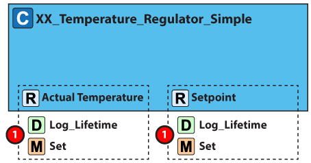
2. Go to the type XX-Temperature_regulator_simple.
3. In the subcomponent section, find the register "Setpoint" and set Log_Lifetime to "One_week".
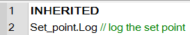
You update the setpoint through the view that activates the get/set-handler.
Hence, you do not need to add any additional code.
You log data when you call the register‘s set-method or when you activate the get/set handler.
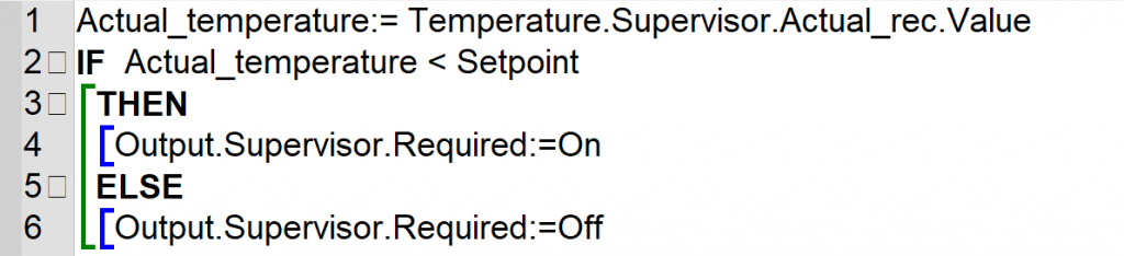
The call to the set method happens when you write data to the temperature register. Look at the first line in the regulate method.
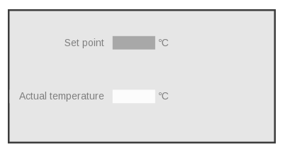
Step 3: Add a view
VIGO6visualization of a register has a window that shows log data. You open the window when you press and hold the left mouse button for two to three seconds. So you don’t have to adjust the view that you have already created.
Step 4: Adjust your testbed
Replace the input (a 4-20mA slider) with a temperature regulator simulator. Orange wire to terminal 01, red wire to terminal 10 and black wire to terminal 30(GND).
The temperature regulator simulator adjusts itself to the setpoint.
Step 5: Download your code and test your regulator
1. Save and build the project and download it to the testbed. Now your display PC will show you the view.
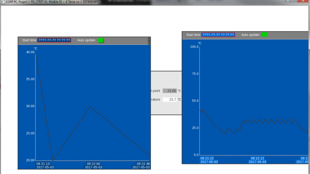
2. You can change the setpoint and see how the temperature adjusts.
3. Open the temperature log view and see the result.
SEE HOW IT WORKS
Now let us move to the next tutorial where you learn how to use the supervisor/servant notification model