Tutorial 7: Control mode, error states and conditions
Let’s learn more about the process component.
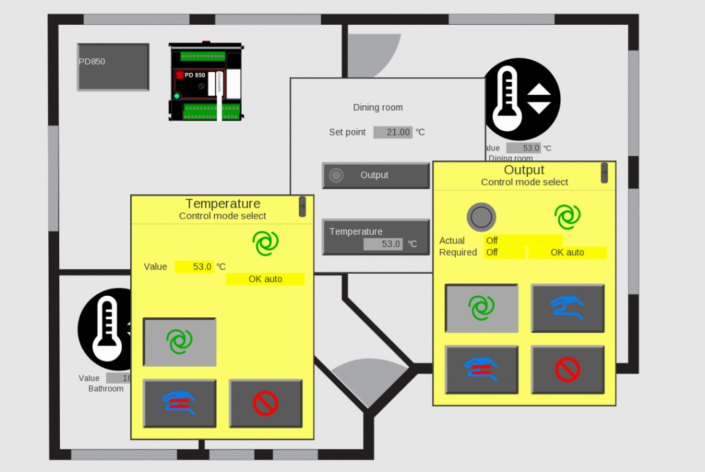
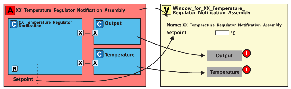
We will build this:
The diagram below shows what you will build in this tutorial. The red dots show the steps.
Control modes
When a process component is a servant, the supervisor controls the servant by Required.
However, you can control the servant in another way. You define it in the control mode. You can find the control mode in the type Control_mode (PD_7575)
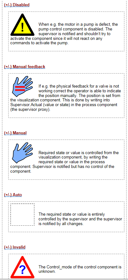
To clarify, the control modes are: – Disabled: Out of service, which tells the supervisor not to use the servant. – Manual_feedback: The operator sets the feedback state. – Manuel: The operator sets the required state. – Auto: The supervisor controls the servant. – Invalid: The value of the control state is invalid.
You can change the mode from the view using set or get Control_mode.
Error and acknowledge
A servant is often in run mode. In the event of an error, it changes to error mode. You can see the error mode in the Qbool array: Error_state_data, GUID PD_9560
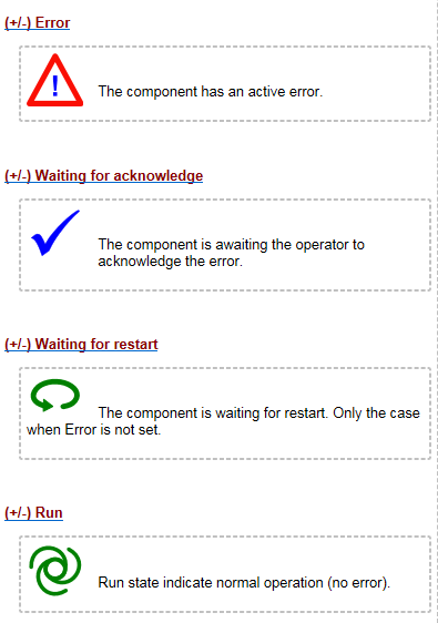
The error states are: • Run • Waiting for restart • Waiting for acknowledge • Error
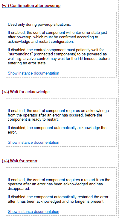
Operator error confirmation
After you clear an error, the component can react in three ways. It is defined in Operator_error confirmation (PD_9557):
– Wait for restart – Wait for acknowledge – Confirmation after power-up.
The view uses set/get Acknowledge error and restart. You use acknowledge when the operator must tell the system that the error is seen. You use restart when a restart needs operator attention.
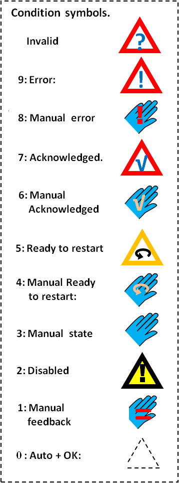
Condition states
The condition of a component is in an enum, PD7883. The superviser and view uses it.
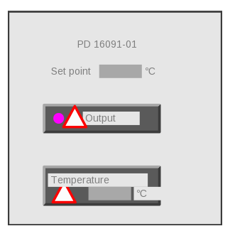
3. Remove the existing view element for the actual temperature "Temperature.Supervisor.Actual_rec.Value".
Now let’s add the buttons: 4. Add button for temperature input a. Right-click on view list and add – view for control component. b. Double-click on control component "Temperature_input_4_to_20_mA ". c. Select view "PD_17593- Show_Temperature_input_4_to_20_mA_as_Pushbutton".
5. Add button for digital output a. Right-click on view list and add – view for control component. b. Double-click on control component "Digital_1A_DC_output". c. Select view "PD_17610- Show_Digital_1A_DC_output_as_pushbutton".
6. Run the graphic editor and move your components around.