How you work in VIGO6 and how VIGO6 works for you
In this section, we will show you our preferred design principles, when you build process automation with VIGO6.
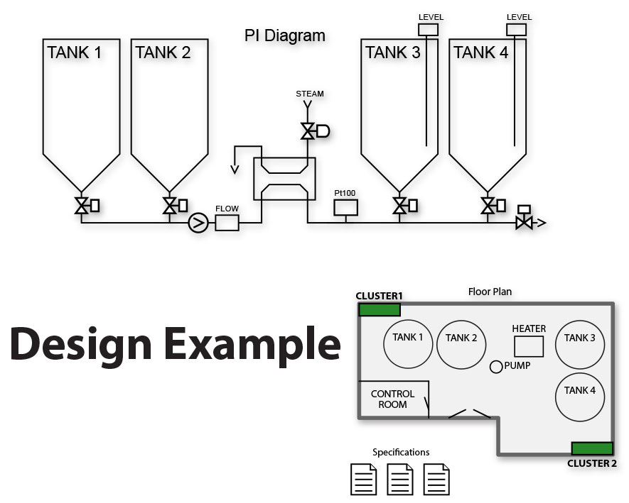
1. Specifications
The first step in any automation project is to get an overview of the requirements.
You can get requirements from floor plans, mechanical drawings,
PI diagrams, and functional descriptions, for example.
You can use these requirements as a basis when you create projects in VIGO6.
2. Drag and drop
As a process engineer, you can easily drag and drop premade process components from an archive. The components represent the various parts of your plant. You can connect the process components with connectors to visualize the connection between parts of the plant. Another example is to use the connectors to visualize the flow of materials.
You need to set the parameters for your process components in your system, like tank size or maximum temperature. Afterward, your VIGO6 project is ready for an offline test and simulation. You can use simulation as the first test of the integrated visualization and user interface without any hardware.
3. Place process components in clusters
As a project engineer, you can distribute all process components that need I/O in clusters by drag and drop. It is important to think about, how to get the easiest cable routing and shortest cable length.
4. Cluster layout and network configuration
You can get lists of the hardware modules you need for each cluster in VIGO6 – and display it in a view – virtually on DIN rails.
The lists suggest the best suitable hardware configuration, and they link the process components to the inputs or outputs within the I/O modules.
VIGO6 automatically adds an Ethernet interface module to each cluster. You can see the types and number of COPP-modules that you need for the project. After the list is generated, you can add, move, or change modules manually. COPP-modules have one or more communication interfaces. You connect all modules in VIGO6 to the desired network(s).
5. Create wiring lists
VIGO6 generates the wiring list. The wiring list has the names you give to each process component during the project creation phase. We have designed the COPP-modules for one terminal for each wire – this removes the need for extra marshalling terminals. The device details can have a part number and other central information.
VIGO6 sends the designation of terminals to the modules that enables the system to show an updated connection overview for each device.
When you have completed the wiring, the modules are ready for download. The download automatically configures the modules. You can now do an I/O test.
6. Develop and configure control components
You can use the archive of control components from PROCES-DATA’s to create your own component. You can use the component as is or change it when you inherit from an existing one. Furthermore, you can change or extend its use, as you want.
You can edit a view for both a control and process component. In addition, you can adjust a user interface to show all – or some – of the total HMI. You can show a view on a PC, touch display, smartphone, and tablet, without any reprogramming.
All COPP-modules can run COPP-code. Depending on the type, complexity and specific requirements, you can locate control components in one module or distribute them in several modules.
You can locate a standard and custom control component in an I/O module. An I/O module can work as a standalone unit. As a result, it can provide higher robustness and fast response to critical local signals.
You can group and store components in assemblies, as a sub plant or even as a complete plant. This grouping lets you create complete systems by the reuse of assemblies or entire plants.