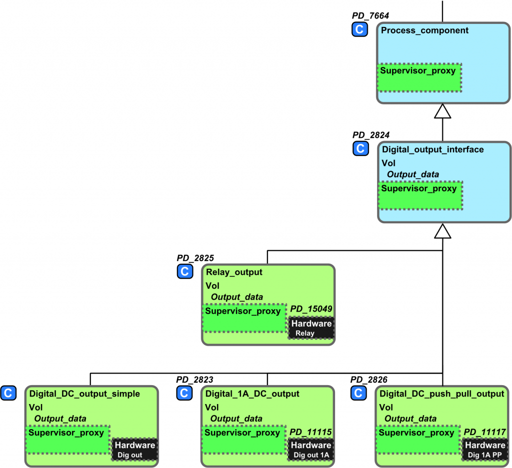
In VIGO6, you do not need to know the specific final design of your outputs or inputs for that matter. You can develop all your control code without deciding which type of digital output to use.
In your control component, you add a connector or servant proxy to ” PD_2824-xx – Digital_output_base”. Now your control code can interface to any of the descendants of the digital output_base. This is illustrated in green color in the inheritance diagram below.

Now you can write your control code that controls the (generic) output.
You can also see tutorial 1:
Once you have made the decision about the type of output, you can proceed. Let us assume that you have selected a relay output.
In your assembly you simply:
- Add the relay output component(PD-2825) and your control component.
- Connect the two
- Locate the relay and control component in PD850 (or in another suitable device)
You can also see tutorial 2:


