Field application update
How to make updates to your live systems
Program download with PD 688
If you require new features or program changes in a project, and you want to use a PD 688 as a device for download, then you can do the following steps.
STEP 1:
Make the updates you want to your project.
STEP 2: Prepare the downloader PD 688
- Add a new device as PD 688 to your project assembly and give it a proper name.
- Connect the new PD 688 to your chosen network, for example, IP.
- Add a visualization for the Configurator (PD_3184-xx – View_for_Configurator) as a Guest view for the new PD 688.
- Insert the right serial number for the new PD 688 in your VIGO6 project.
- Build the project.
- Download the Customware to the PD 688 and see that the download screen shows on the PD 688.
- Copy the ‘Output’ folder from the project folder in your VIGO6 library to an SD card. You have to place the ‘Output’ folder in the root of the SD card with the name ‘Output’.
- Insert the SD card in the PD 688.
STEP 3: Use the PD 688 for download
- Connect the new PD 688 to the running system in the field via the desired network.
- Switch on power for the new PD 688.
- Press the button for ‘Config all modules’ and the PD688 will download new customware to all devices in the running system.
- Your running system now contains the new Customware.
Hardware modules
Tips on the COPP hardware modules and peripherals
The hardware-interface PD_16494-06 – Power_state_notification_interface is a subcomponent. You can add it to all the components where you want to handle changes in the power state.
When the power state changes, you get a notification. Further, you get the current power state in the local variable “events”. One of these states is “External_power_lost”. In other words, you get this event, when you lose the main supply, and your device runs on a battery.
See the small basic example below.
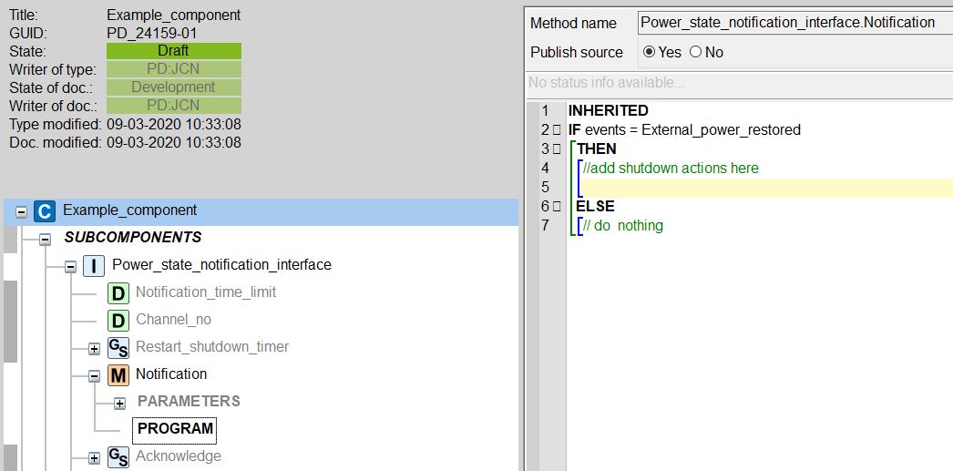
Nb. Once you add the interface you can only locate your component in devices with batteries (i.e. PD 688, PD 803, and PD 802).
Reset button and diode
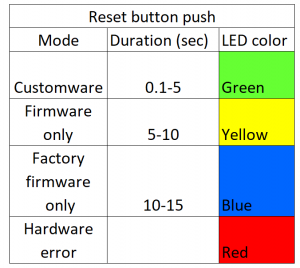
You use the reset button to reset a module or change its mode. The module’s diode will show its mode. When you press the button, the diode will turn off for 100 ms as a response. You can make the diode blink through a method call.
Customware
After a normal reset, the module will run the firmware and customware that you have downloaded to it, and the diode will show a green color.
Events that trigger a normal reset:
– A power failure.
– A P-NET call to a “reset”-method.
– A press under five seconds on the reset button.
Firmware only mode
If a customware program on a module causes an error, you can start the module in “firmware only” mode. The module will never call the guest component, only the firmware. Now, you can download new customware and activate that instead.
You change to “firmware only” mode with a press on the reset button for five to ten seconds. The color of the diode will be yellow.
Factory only mode
This mode is for when you have a major problem where you can’t even connect to the module in “firmware only” mode. In that case, you force the module to run its factory firmware. As a result, the module will lose its non-volatile data, including the P-NET settings. The factory firmware is the firmware it had when the module left PROCES-DATA.
You change to “factory only” mode with a long press on the reset button for ten to fifteen seconds. The diode will be blue.
Dead or busy
The diode is a constant red, and you can’t change its mode. The module needs service.
Download
The active customware on your module runs, while you download to it. In effect, the downtime for the module is short.
Power-up while you press the reset button
It will activate “factory only” mode. You can use it to mount a module that you have already used for another purpose. You install the module in a plant with a power supply, while you press and hold the reset button down. Afterward, it will not interfere with the communication in your system, because you reset its P-NET settings.
The table has an oveview of the different presses and the colors.
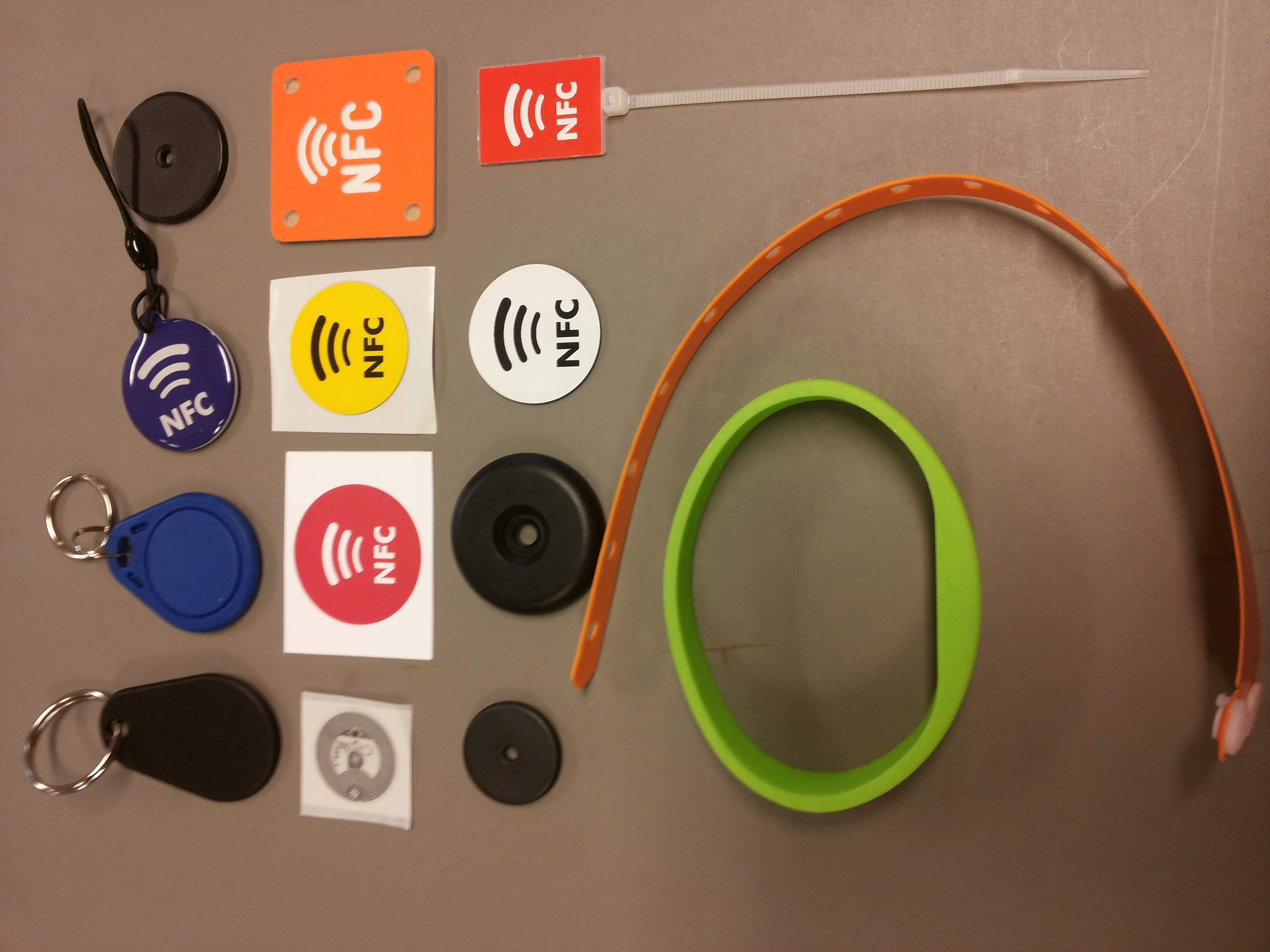
You can use:
- cards
- bracelets
- key hangers
- stickers
Or any other vessel that contains a TAG of type:
- NTAG210 (Mifare Ultralight)
- NTAG213
- NTAG 214
- NTAG216.
| You need a PD688 or a PD803 to be able to print from VIGO6.
The printer must:
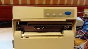
We have tested two printers: EPSON TM-T88V-042 model M244A |
 |
| CITIZEN model CT-P293 |
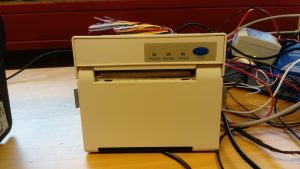 |
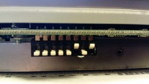
| Special note for the CITIZEN printer. The switches must be set as in the pictures below in order to function correctly. |
  |
IT and Support
When something does not work, look here
Your PD-contact person can help you sort out what kind of support you need, and what is appropriate for your specific problem.
If we need our VIGO6-experts to have a look at your problem, they will typically ask for a support file.
Instructions on how to generate a support file:
Contact salesdepartment@proces-data.com. You can also press the red tab on the right-hand side of this screen and fill in the form.
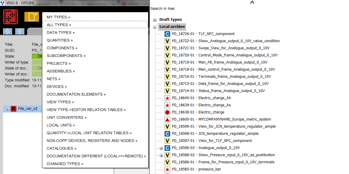
You can continue working offline on all the content in your local archive. Once you are back online, you can then push your work to the company’s archive (signer archive) for safekeeping. You can find the content of your local and company archive in the editor by selecting “open”-> “All types”.
In addition, the section “Draft types” contains a subset of the local archive. It holds all the types you are the writer of, and that you have not yet pushed to the company archive. It means that anything in the “Draft types”-section only exists on your local PC.
PROCES-DATA hosts your VIGO6 server. It communicates with TCP on port 35349. In short, change the company’s firewall settings to allow communication on that port, and you are ok.
We have the following minimum recommendations for the workstation used to run the VIGO6-editor:
- Minimum 3,6 GHz CPU
- Minimum 6 GB RAM
- An SSD-disk
Especially the SSD disk is important for speed. We have seen 50-60 times speed improvements between using a non-SSD-disk and an SSD-disk.
Programming
Understand the elements of VIGO6 and the COPP programming language.
| While PROCES-DATA has designed the modules for 4-20mA inputs and outputs, it is still possible to use a 0-10V input.
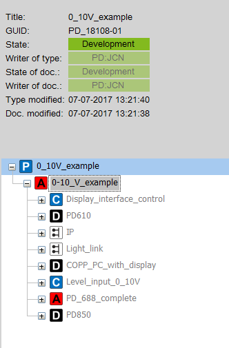
Below is an example of a 0-10V level input transforming the 0-10V input signal to a length. We have implemented basic error handling, which means that it will signal to its supervisor if it has an error. You can operate it in “manual feedback”, “auto” and “disabled”. For more info on the built-in functionality of the process component see tutorial 7. The component is PD-18096 and in the documentation section, you can see what it does. Basically, it reads a voltage and converts it to meters. We have also created a view for the component (PD-18048) and for the assembly (PD-18117). But, you have the possibility to create your own too. As we have mentioned in the documentation for the component, you can only locate it in a PD850. Additionally, you need to set operator rights in order to edit and see the view. If you do not add any operator control, you will likely not see any fields on the views we have made. That is why we have added component PD-17553 Display interface control to the assembly. In effect, we can add the login or logout button to our assembly view. This enables us to play around with operator rights. To see how you can use the component, there is a project with the GUID PD-18108. |
 |
| If you want to interface to this component in your overall control component, then do it as a “supervisor-servant”-connection. Below you see how to access the “level in meters” |
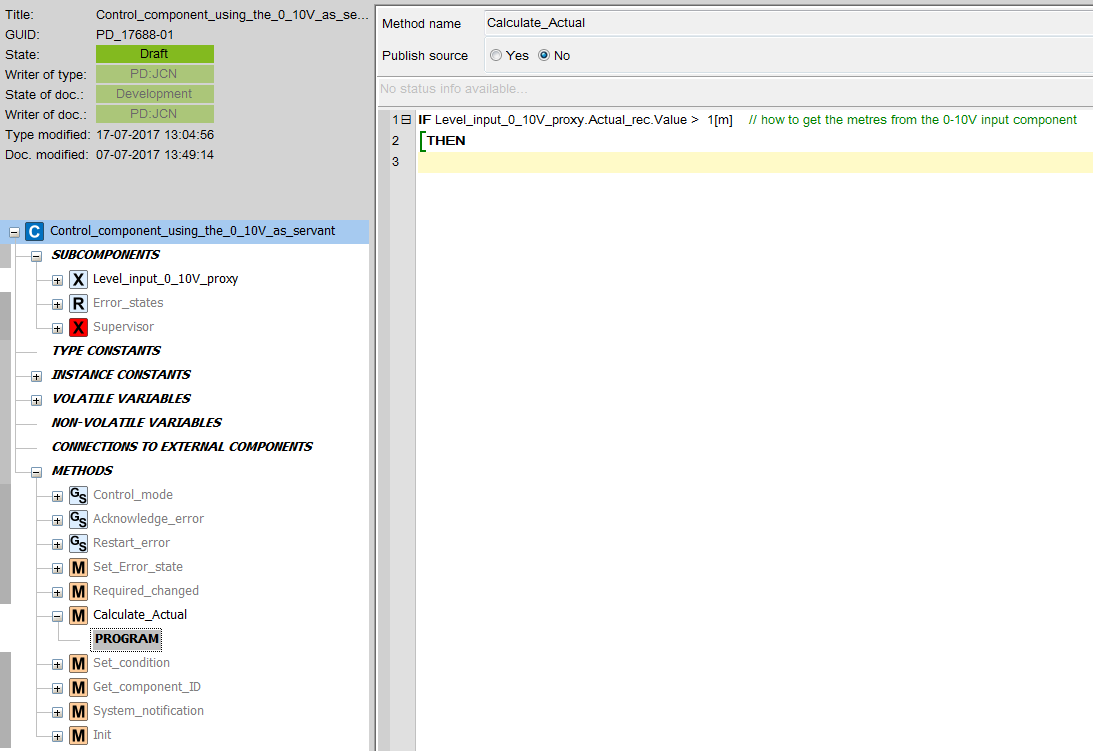 |
| First, locate your components into devices – which will give you the automatic configuration. The method is that the first output you add gets the first output channel. The first input you add gets the first input channel etc. The system only allocates to an I/O channel, when all I-channels are full.
You can change the allocation:
If you have “filled” all channels in the device, you can start by clearing the channel number on a few of the components, so you have space to move around. |
 |
Using one of the predefined “Quantity <-> local units relation table”
All units in VIGO6 are stored as SI-units but can be displayed as any derived unit you want.
Volume in Litres and flow rate in liters per second are already defined and are e.g. used in the “quantity <-> local units relation table” PD_12849 Europe_metric_system_MID. So if you select that one in both the project and editor, you will work in liters instead of m3.
Creating your own derived quantity
If you want eg liters per minute, you first need to create your own local unit.
Open PD_13598 Volume_flowrate_l/s. Rightclick and select “create new type” now rename this new type to “Volume_flowrate_l/minute” and adjust the symbol to “l/m” and the scale to 60000 (1000 to go from M3/s to l/s and another 60 to go from l/s to l/m)
You then need to create your own “quantity <-> local units relation table”.
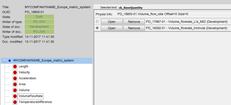
Open PD_12849 Europe_metric_system_MID. Right-click and press “create new type”. Rename to eg” MYCOMPANYNAME_europe_metric_system”
Then you right-click on “VolumeFlowRate” and select “Add local unit type” and choose the “volume_flowrate_l/minute” you just created. And then you press on the radio button next to your own unit.
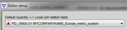
The final step is then to select this new “quantity <-> local units relation table” in your project(right-click on the project name and select “quantity <-> local units relation table”).
You should also add it in your editor (set on the setup screen).
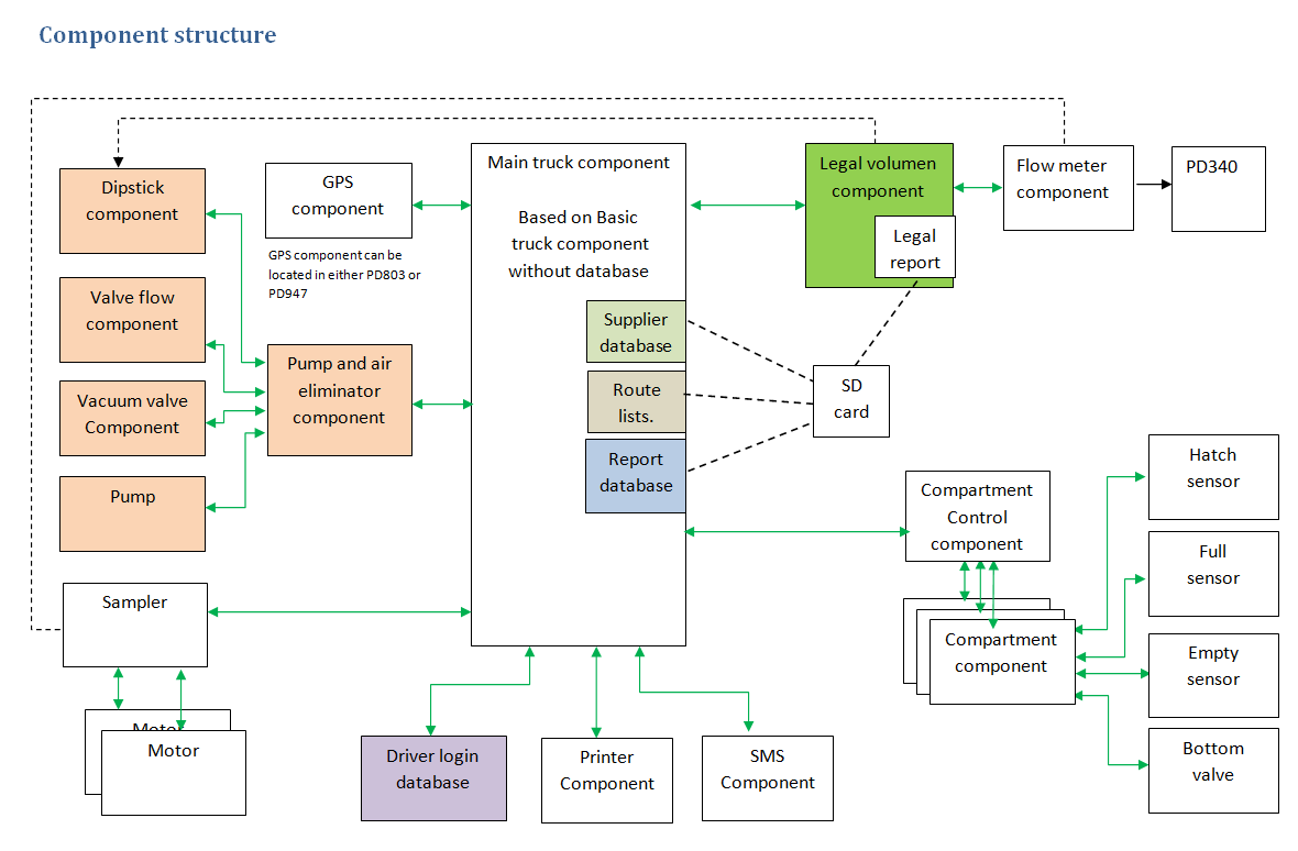
Overall design
In general, PD recommends creating components for “logical functions”. As an example, please see the below component structure for a milk tanker system. By following this method, you can use a broad range of physical components such as pumps and valves. You can even use a combination of them, without having to change any program code. We have made a demo-project PD_17604-02 that implements the described component structure.
Using methods to reduce the number of program lines
Sometimes you find that a method becomes so large that you find it difficult to read. In that case, you have the option to create methods within the component, that you can call from your “too large” method. An example is a functionality used in many places. Another example is to make a method for each state in a state machine. In the end, remember that you can make a supervisor/servant-connection from one component to another. As a result, you can get access to the methods and data in another component.
When you work together on a project in the early stage, it is faster and simpler to use the shared draft state. Use it for both the project as well as the types you use in the project.
You need to share all the types with the people working on the project. They can see and use them, but there is still only one owner. You create a project. Different people can work on different types that you use in the project. As a rule of thumb, split the project into as small pieces as you can. In that way, you don’t have to wait too long for other participants to implement changes.
If you find an error or want to add functionality to one of the types, the type owner can make the changes. Afterward, the type owner should push the types to the shared draft again. You can then go to the specific type and restore type and documentation, and thereby you implement the changes in the project.
You don’t need to create new versions of all the connectors and views for the type. It is primarily of that reason that it is faster and simpler.
There is no notification system in the editor that gives you an update when there are changes to one of the types in the project. As a result, you need to be in a close dialog with your colleagues.
Everyone who contributes to the projects needs to have the same editor version.
In VIGO6, you do not need to know the specific final design of your outputs or inputs for that matter. You can develop all your control code without deciding which type of digital output to use.
In your control component, you add a connector or servant proxy to ” PD_2824-xx – Digital_output_base”. Now your control code can interface to any of the descendants of the digital output_base. This is illustrated in green color in the inheritance diagram below.
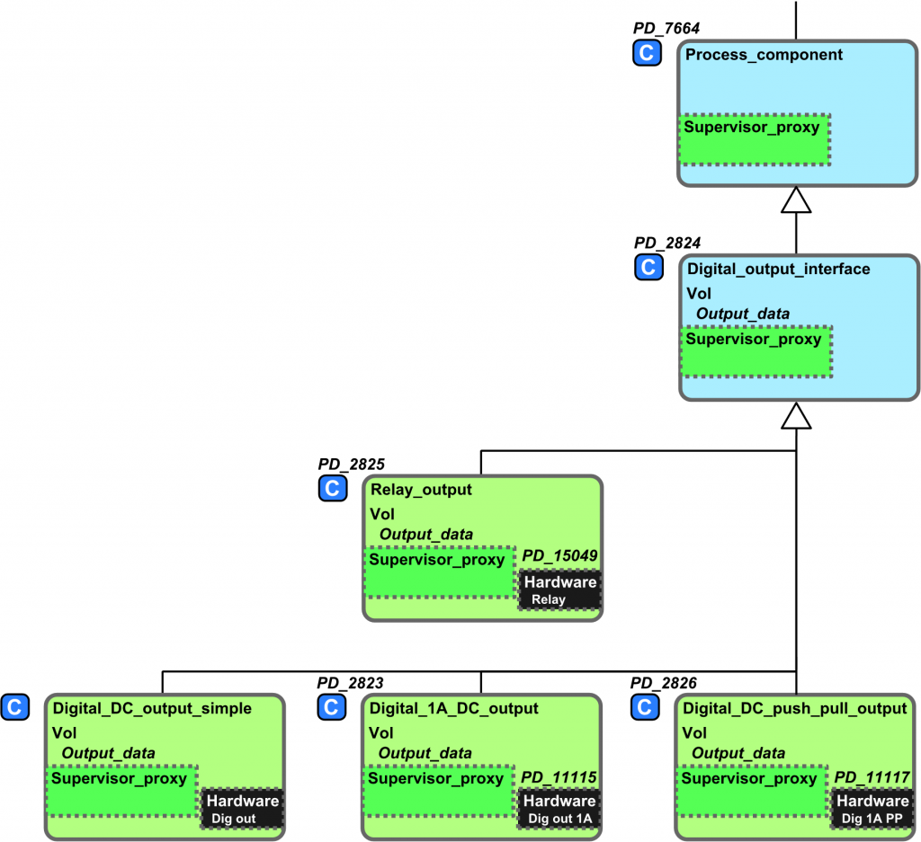
Now you can write your control code that controls the (generic) output.
You can also see tutorial 1:
Once you have made the decision about the type of output, you can proceed. Let us assume that you have selected a relay output.
In your assembly you simply:
- Add the relay output component(PD-2825) and your control component.
- Connect the two
- Locate the relay and control component in PD850 (or in another suitable device)
You can also see tutorial 2:
The programming language in VIGO6, called COPP, is similar to PROCESS-PASCAL, so this part should be no problem.
And the VIGO6 platform contains many improvements that will make development easier, including:
- In VIGO6 you build and test functionality one time, and then you can use it again. No copy-paste – you just add the component to your assembly.
- In VIGO6 you have a lot of premade components that you can use in your project. It can be a pump valve or flow meter components.
- In VIGO6, you tie the visualization to a component or assembly, and you can reuse it.
- In VIGO6, you have better options for the maintenance of existing systems. There are no settings done directly on the modules – as was the case in VIGO5. As a result, when you locate your project for the system, you know what is running, can make the updates you want, and then build and download the new program.
- In VIGO6 you can replace a faulty module on-the-fly. You simply remove the faulty module and plug in a new one, type in the Serial Number of the new module and you are back in business.
See also advantages in VIGO6.
While we suggest using the NFC-reader in the PD688 display unit for easy login, you can also predefine users.
We have created a control component (PD_17553) and visualization (PD_18202) that allow you to create six default users for every display unit in a project. These are instance constants in the control component, so once you have added the component to your project you simply define the default users you want. And of course, remember to locate the component into the display unit.
The user logs in with username + password OR with userID + password.
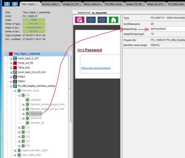
The password and username are a (text)string. The string value is entered as plain text in the “AdaptString” cell.
See the example for Operator [0].
NoOfElements is the string length, 0,1,2,3 … is the elements of the string. So since NoOfElements is 20, the password can be up to 20 characters long.
Tip:
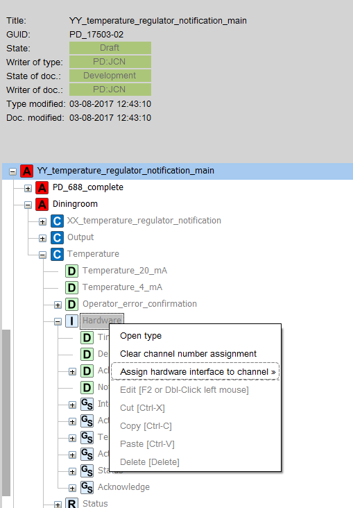
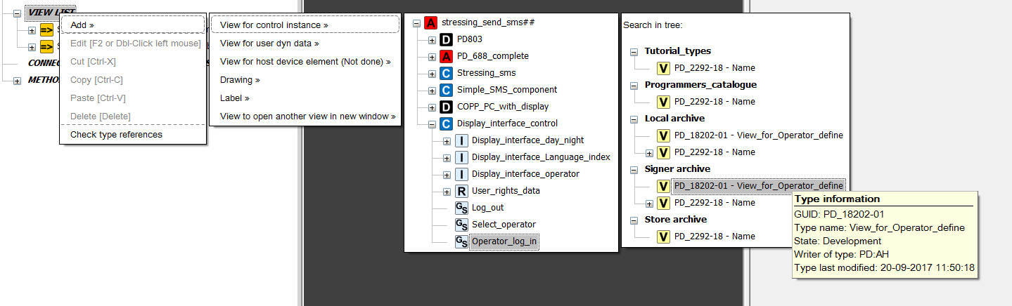
To add the visualization, you need to find the get/set method of the “Operator_log_in” (see the attached screen dump)
Visualisation
Tips and tricks on building awesome visualisations for your components and assemblies
Yes, you can. Please see this tutorial, where you will get detailed instructions on how to create your own keyboard.
Have a look at tutorial 6:
It explains how to add either standard buttons or custom made buttons
NB! The view always opens in its built-in size. It means, there is no “show on full screen”-mode. But as long as you design your view for your maximum screen size you will get the effect you want.
This can be done in VIGO6 via a pre-built component.
Check this tutorial upon language and operator access rights!
Yes, this is “as designed”.
But of course, you have several options to change the default behavior of the screens. Just refer to this tutorial!