Component Oriented Process Programming
• Safe and efficient design of control systems using tested and approved elements.
• Elements are software components for control of mechanical and electrical
equipment and their visualizations.
Basic VIGO6 design concepts – Control component – tying mechanics and views together
In VIGO6, you build your control system with control components programmed in COPP – short for Component Oriented Process Programming. Control components are designed to control physical parts.
The control components are visualized by views created for them.
PROCES-DATA has designed a large number of control components with views. These components are used as building blocks to create a complete control system. When you need a component that is not available, you program your own component, which can inherit from an existing component.
Input control
Example of a general digital input component electrically connected to a micro switch.
The input control component detects logical input states, measures input voltages, counts pulses, etc.
The views for such an input component show the input state, measured input voltage, counter etc.
They show the physical module ID in which the input is located and terminal numbers where to connect the wires.
The input component can have more views that illustrate the mechanical unit connected to the input, in this example an image of a micro switch, showing its position.
Output control
Example of a general output control component is made for controlling the voltage to an external load. It can control outputs like solenoid valve, relay or lamp.
The output component controls the voltage on its output, measures the current in the output, generates pulses, disconnects by overload etc.
The views for such an output component show the output state, measured output current, errors, physical module ID in which the output is located and terminal numbers where to connect the wires. The output component can have more views that illustrate the different mechanical units connected to the input. In this example an image of a solenoid valve, showing its state.
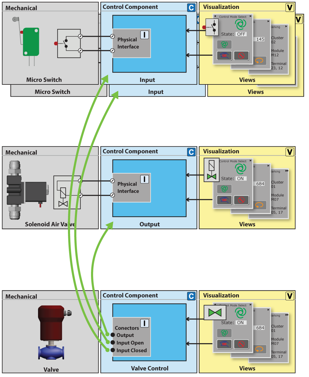
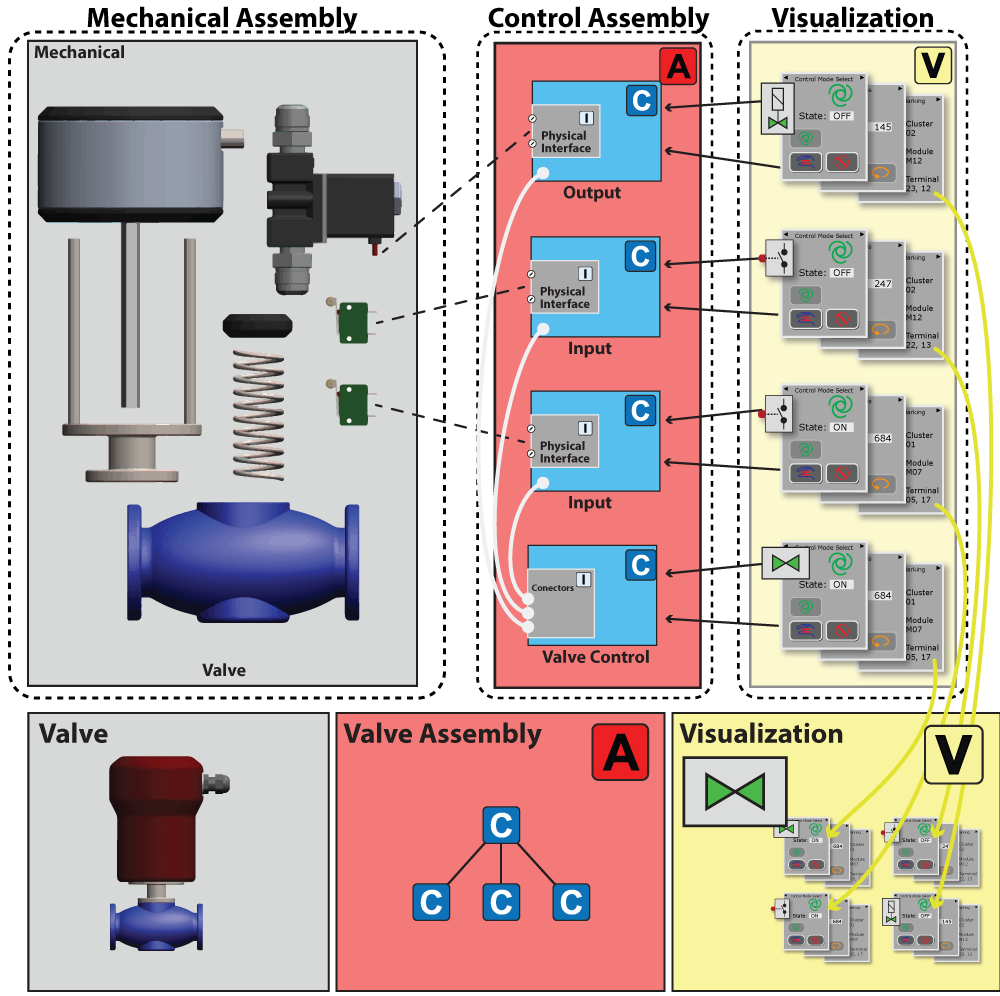
An assembly of control components
Control component for an air operated process valve.
• The process valve opens by activating a solenoid valve.
• A micro switch is activated when the valve is open.
• Another micro switch is activated when the valve is closed.
The task of a process valve control component is to receive commands for opening / closing the valve and report the valve state, including errors.
The valve control is designed to be connected to an output and two inputs and to control the output and read the inputs.
Relation between mechanics, control and visualization is as follows:
A mechanical valve is an assembly of mechanical components put together, according to an assembly drawing for this type of valve.
The control components, for controlling the mechanical valve, are similarly defined in a control component assembly type.
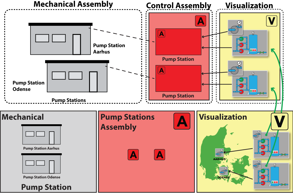
Building a pump station assembly using existing assemblies.
An assembly is created for each physical part, and they are all gathered in an assembly with one control component for the whole pump station.
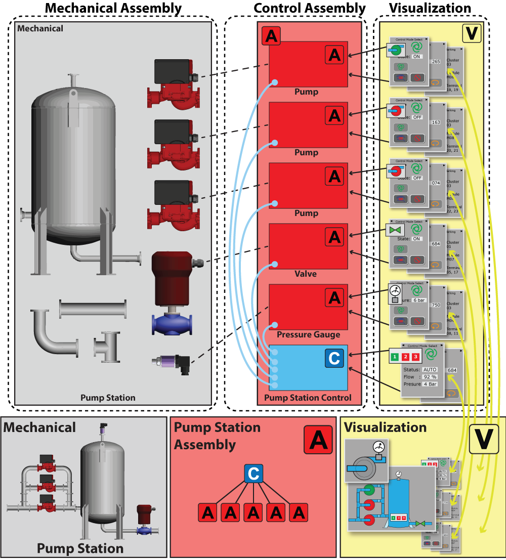
A pump station assembly is created by including 3 pump assemblies, a valve assembly and a pump station control component. The visualization of the whole pump station is based on the visualization of the pump assembly, the valve assembly and the control component.
The example below shows an assembly with two pump stations of the pump station type at different locations.
The two pump stations are remote controlled by a general visualization, containing two pump station visualizations.