Tutorial 5:
Creating views in views - and reusing control components and assemblies

We have built a component that uses the supervisor/servant notification model. Now, let’s learn how to create views

What we want to build – logic:
A house control where two rooms have a temperature regulator in them.

What we want to build – visual:
1. A view that shows a floor plan of a house, with a temperature regulator in two of the rooms.

2. The actual temperature should be visible in the overview picture.

3. When we press on the temperature regulator icon, a window opens that shows the setpoint (editable) and the actual temperature (read-only). We will also show the name of the (instance of the) assembly.

Lorem ipsum dolor sit amet, consectetur adipiscing elit. Ut elit tellus, luctus nec ullamcorper mattis, pulvinar dapibus leo.

We will reuse the window we created in tutorial 4 for the assembly with supervisor/servant notification:

This will be the window that opens, so all we need to build is the "button" that opens this window.
The diagram below shows what you will build in this tutorial. The red dots show tutorial steps.

Before we start building, here are some facts about how to work with views.

You can create views for:
• Data types (which we will see examples of in tutorial 7)
• Devices (which we will do in tutorial 6)
• Components (as we did in tutorial 1)
• Assemblies (as we did in tutorial 4)
• Main assemblies (which we will do later in this tutorial.
NB: You can’t create views for projects.

FACTS
You can design as many views as you want for a given component or assembly.
• The elements that you can visualize are registers and (results of) Get/Set-methods (which will often return one or more values).
• You can add drawings (in SVG-format) as we will do later in this tutorial.
• You can also add labels – that you can use to show "fixed text" information.
• And finally, you can add existing views, so your view can be a mix of existing views and your own.

RULES OF THUMP
You can only visualize what the component or assembly has access to, so as a rule of thumb you create:

• Main Assembly views to visualize your total project functionality.
Assembly views to show the functionality of a component that connects to other components (as e.g the view we created in tutorial 4).
• Component views if your component has all the information inside itself – possibly by reading the information from others into registers (as we did in tutorial 1).
Device views to visualize any device-related information (serial numbers, wiring info, the temperature of the module, etc.).
• Data type views to visualize data such as e.g. enumerated types, registers, etc.

Step 1: Create the button

Creating a view for the button
The button is created as a new view for our assembly "XX_Temperature_regulator_notification_assembly"

1. Open the assembly.

2. Right-click and select "create new view for this type based on PD_13556 – asm_view".

3. Rename to "button_for_XX_Temperature_regulator_notification_assembly".

4. Set view region – bottom right to y=50[mm] and x=50[mm]

5. Right-click on the view list and add drawing PD_17418- Temperature_Regulator

6. Add temperature view
a. Right-click on the view list and add "view for control instance".
b. Press on temperature- actual rec – value (which represent actual temperature).
c. Select view type PD_2159- Number_name_value_unit.

6. Add temperature view
a. Right-click on the view list and add "view for control instance".
b. Press on temperature- actual rec – value (which represent actual temperature).
c. Select view type PD_2159- Number_name_value_unit.

Creating a view for the button

1. Save the view and launch the graphic editor.
Your view will look something like this:

This is because your drawing is a bit bigger than the view area defined, so you need to scale it.

Scaling the button

2. Click in the black part of the view – this will select the drawing in the editor.

3. Switch to the editor and set scale factor 0.4

4. Now move your view elements around, so they look something like this:

Configure your button

Now you need to indicate which window to open when you press the button. And here we will reuse the view we made in tutorial 4.

1. Insert an open view field
a. Right-click on view and add view to open another view in new window.
b. Select: PD_16706 – Open_view_in_new_window.

2. Select view to open
a. Right-click on the Open Info.
b. Press "view to open" -> "Select" -> view for control instance.
c. Double-click on the assembly"XX_Temperature_Regulator_notification_assembly"
d. Select "Window_for_XX_Temperature_Regulator_notification_assembly".

3. The last thing you need to do is to make sure the window opens, no matter where the user clicks on the button.
a. For all elements in the view list, except the "open view in new window" mark the parameter "disable hit test".
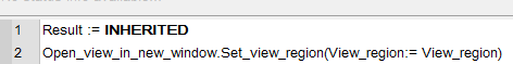
b. Find the view method " get view region".
c. Press override. Add this code line: Open_view_in_new_window.Set_view_region(View_region:= View_region)

What your code should look like:

Now all mouse clicks or screen taps will go to the "open view in new window".

NB! You can’t use the graphic editor to view your button now. This is because the view region calculation uses methods that are only available at run-time.

SEE HOW IT WORKS

Step 2: Add a new instance of your temperature assembly

We need two instances of the temperature regulator. We want to display their names, so you need to update the existing main assembly.

1. Open your main assembly from tutorial 4, ie. XX_Temperature_regulator_notification_main.

2. Rename the assembly instance "XX_temperature_regulator_notification_assembly" to "Bathroom"

3. Add a ‘room’.
a. Add a new instance of assembly "XX_temperature_regulator_notification_assembly".
b. Rename it to "Dining room".

4. Locate the new control components on PD 850.

5. On your testbed, connect a temperature regulator to terminal 11 / 31 and a DC output to terminal 2 / 22.

Here we see one of the powerful features in VIGO6. We have built a complex functionality (the temperature regulator assembly) once, and we could reuse instances of it easily. Simply by adding a new instance to our assembly (and eventually wiring up any I/O).

SEE HOW IT WORKS

Step 3: Build the main view

We are now ready to build our main view using the building blocks we just created.

1. Right-click and select "Create new view for this type based on" and select "PD_13556 Asm_view".

2. Rename to "XX_Main_view_with_house_and_regulators".

3. Set view region bottom right y=200[mm] and x= 300[mm].

4. Right-click on view list and add:
a. Drawing: PD_17425 Plan_Drawing_Tutorial. Set the scale factor to 1.8.
b. View for control instance: find and double-click on assembly "Bathroom" and select the view "button_for_XX_Temperature_regulator_notification_assembly". Set the scale factor to 0.9.
c. View for control instance: find and double click on  assembly "Dining room" and select the view "button_for_XX_Temperature_regulator_notification_assembly". 
Set the scale factor to 0.9.

Save the view and launch the graphic editor. Now drag the elements around to find suitable rooms for your icons/buttons.

Your view should look something like this:

SEE HOW IT WORKS

Step 4: Build and run your project

1. Now open your project "XX_Temperature_regulator_notification_project".

2. Change visualization.
a. Right-click on your main assembly and press "open type". This changes your perspective to the main assembly.
b. Now that you are in the main assembly, find the guest view on the device "COPP PC with display", delete the existing view and add your new view "XX_Main_view_with_house_and_regulators".
c. Find back to the project, by clicking back (Ctrl+B or using the Back button).

3. Save, build and run your project on the testbed.

Make sure to click on the regulator buttons to see your windows open and test your two regulator instances via the testbed.

SEE HOW IT WORKS

Having created a temperature regulator assembly with a button and a popup-window, we can now easily use instances of this in other projects on different types of hardware modules.

If we are not happy with the view, we can always create new views for the assembly and/or the main assembly or change existing views by inheriting or cloning.

Now let us move to the next tutorial where you learn how to
add a few more elements to the main assembly view we have just created